background image

15

4.0 Structure a n d fun ctio n

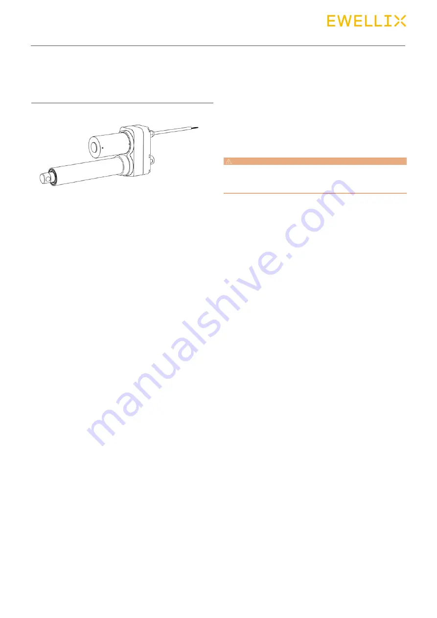
4.2  Brief description

Overview

This actuator is to be used exclusively for installation into a 
dynamic centric-compression or tensile-loaded lift.

The linear actuator consists of a motor part (4), a gear unit 
(7) and a linear unit (3), connected with each other.

The actuator consists of a direct current motor with helical 
gear which sets in motion a gear transmission system. Via 
the driving screw and nut, the rotation of gear is transformed 
into a linear motion of the actuator.

The front hinge head (1) and the rear hinge head (6) transmit 
the actuator power to both sides of the application.

Depending the CAHB-2xE version, the extension tube can 
rotate and must be fasten on the application to avoid the ro-
tation and provide the linear movement. In option for the 
CAHB-2xE, the tube can get an anti rotation. The anti-rota-
tion of the tube is a standard feature of the CAHB-2xS

Fig. 11

4.3  Special features

Mechanical overload protection

The actuator contains a mechanical overload protection unit 
(clutch).This overload protection unit will activate if the linear 
unit of the actuator overloads. This activation will avoid to 
push or pull over the maximum force defined on the data-
sheet and will protect the motor and gear unit from being 
damaged.

CAUTION

Continued operation of the clutch can result in overheating and 

damage to the linear actuator. If clutch activates, switch off power 

immediately.

Integrated controller (S design only)

The smart version has a built-in electronics controller with 
H-bridge and 2 micro controllers . This integrated controller 
provides multiple functions described bellow.

Unique true absolute position sensor  
(S design only)

A unique absolute positioning system equipped all smart 
CAHB-2xS . Based on gears and no contact sensors, the 
tube position generate an absolute signal in-stead of an in-
cremental signal. The actuator will never lose the position 
even if the tube of the actuator is moving when the actuator 
is not powered. No need of calibration to keep the full per-
formance during the ac-tuator life.

Electronic overload protection  
(S design only)

An electronics over load protection limits the current draw by 
a current cut-off, so the force that the actuator can push or 
pull. The temperature effect on the performance is compen-
sated by the micro controller after a calibration done at the 
end of line test of the actuator assembly line.

Soft start / soft stop (S design only)

The soft start and soft stop with a ramp up and ramp down 
during 200 ms is set on the controller in order to limit the dy-
namic effect of the acceleration and dec-celaration and get 
a smooth movement. 

Summary of Contents for CAHB-2 Series

Page 1: ...CATEGORY MAX 2 LINES CAHB 2x series Linear actuator CAHB 20E and 20S CAHB 21E and 21S CAHB 22E and 22S INSTALLATION OPERATION AND MAINTENANCE MANUAL...

Page 2: ...ted 19 4 6 6 Manual Override 19 4 6 7 Smart CAHB 2xS function 20 5 0 Transport packaging and storage 21 5 1 Safety information for the transport 21 5 1 1 Transport inspection 21 5 1 2 Return to the ma...

Page 3: ...Maintenance 32 9 1 Spare parts 32 9 2 Maintenance plan 32 9 3 Maintenance work 33 9 3 1 Cleaning 33 9 3 2 Inspections and readings 33 9 3 3 Check of visual condition 33 9 4 Measures after completed m...

Page 4: ...the illustrations used are not necessarily to scale and may vary from the ac tual design of the actuator 1 2 Explanation of symbols and signal words Safety precautions Safety precautions are identifie...

Page 5: ...e of unapproved spare parts In case the actuator is customised the actual product deliv ered may be different from what is described in the manual In this case ask Ewellix for any additional instructi...

Page 6: ...require ments of the Occupational Health and Safety Act In addition to the safety instructions in this Manual the owner or processor must do the following concerning these safety and acci dent preven...

Page 7: ...n switch off the power supply immediately and have the parts repaired Work on the electrical system must be carried out only by profes sional electricians De energize the machine for all work on the e...

Page 8: ...erature has fallen below the threshold for the switch to operate A driving screw nut converts the rotation of the gear unit into linear motion If an overload occurs when the actuator is operating a ba...

Page 9: ...perature of the motor will increase and the duty cycle and running time could be decreased 12 V DC version Duration intermittent Information Value Unit Maximum operating time without a break 85 sec Ma...

Page 10: ...n supply voltage For actuator 40 to 55 V DC For Encoder 4 to 20 V DC For Potentiometer Voltage limited by power 2 W For absolute analog position sensor 10 to 55 V DC current consumption 15 mA max S de...

Page 11: ...r 8 Manufacture date 9 Manufacturer or the country of origin 10 CE mark 11 RoHS mark 12 QR code for Operating manual S design Fig 2 1 2 3 4 5 6 7 9 10 11 8 12 The product label provides the following...

Page 12: ...out position feedback 1 Front hinge head 2 Push tube 3 Guiding tube Steel tube 4 Motor 5 Cable 6 Rear hinge head 7 Gearbox Fig 4 CAHB 20 E with position feedback 8 Middle housing Fig 5 CAHB 20 E with...

Page 13: ...ding tube Al alloy tube 4 Motor 5 Cable 6 Rear hinge head 7 Gearbox Fig 7 CAHB 21 E and 22 E Include 3 types outline CAHB 21 E and 22 E with position feedback 8 Middle housing Fig 8 CAHB 21 E and 22 E...

Page 14: ...thout manual override 1 Front hinge head 2 Push tube 3 Guiding tube Al alloy tube 4 Motor 5 Cable 6 Rear hinge head 7 Gearbox Fig 10 CAHB 2x S with manual override 8 Manual override part 4 7 1 2 3 6 5...

Page 15: ...l protect the motor and gear unit from being damaged CAUTION Continued operation of the clutch can result in overheating and damage to the linear actuator If clutch activates switch off power immediat...

Page 16: ...p of actuator that should work at the same length during the complete motion until the stop A command to any actuator of the group will be enough if all actuators were predefined All ac tuators will m...

Page 17: ...r shaft Gear unit is connected to the over load clutch that moves the drive screw system S design The helical gear is directly powered by the motor shaft Gear unit is connected to the drive screw syst...

Page 18: ...0K Fig 15 Potentiometer 4 6 3 Absolute analog position output E design The absolute analog position sensor is a multitude non con tact magnetic sensor It provides a signal indicating the posi tion of...

Page 19: ...he CAHB 2xE a power tool can be used to drive the cover by the hexagon head Don t use a power tool with the manual override of the CAHB 2xS Please control the torque and speed not to exceed the maximu...

Page 20: ...by I O 0 10V or 0 5V absolute analog CAN bus J1939 feedback Actuator length in 1 10 mm Force in N Speed in Flag of Endstop retracted Flag of endstop extended Flag of run in retraction Flag of run in e...

Page 21: ...eed as follows for the return transport 1 Dismantle the actuator if necessary 10 0 Disman tling page 36 2 Pack the actuator in its original packaging Follow stor age conditions 5 2 Storage 3 Send to m...

Page 22: ...articular components that are part of a retrofitting may only be installed in accordance with the re spective instructions circuit diagram The electromagnetic compatibility must be tested for the rout...

Page 23: ...s 3 During installation be sure that the linear actuator is not impacted in its movement over the entire stroke area 4 During installation be sure that the motor cable is not squeezed clamped or pulle...

Page 24: ...own VB Cable Red EXT Cable Black RET VB SW RET D1 D2 S1 S2 SW EXT Motor M A VB VB Limit switch contol VB Cable Red EXT Cable Black RET VB SW RET D1 D2 S1 S2 SW EXT Motor M A VB VB Limit switch contol...

Page 25: ...d Black Red Black Reserved Ret signal Ext signal Analog Analog Power GND Grey Orange Purple Green Brown White Yellow Power Module Output Module CANBus Communication MCU Sensor CAN H CAN L VB VB I O Ex...

Page 26: ...0CFF0103 Control CAN ID 04EF0101 04EF0102 04EF0103 7 2 2 CAN ID in synchronous mode In one CAN bus loop there is allowed only one group of ac tuators in synchronous mode And it s CAN ID is Feedback CA...

Page 27: ...2 Running in retract direction 1 valid 0 invalid bit3 Running in extend direction 1 valid 0 invalid bit4 bit7 Reserved Byte 7 Error Code See 7 3 1 Error Code Description Eliminate error 0 No error 1 C...

Page 28: ...anufacturing 65001 65535 Reserved Set limit drive force to use Byte 2 Byte 3 Force 0 15000 Set limit drive force to use 1 N 0 15000 N 15001 65535 Reserved Set linear speed to use ratio with max speed...

Page 29: ...29 lifetime 100 Not retracting not extending stopped not at end stop position Error code 0 0CFF0101 5C10 D007 1D 64 00 00 CAN ID 0x105C 4188 0xD007 2000 0x1D 29 0x64 100 0x00 0 0x00 0 7 5 2 Control Re...

Page 30: ...amage through overheating Therefore Only use control integrated thermal switch Never exceed nominal load 11 Appendix page 37 Always adhere to idle times and operating times 11 Appen dix page 37 8 2 Ac...

Page 31: ...ncy In hazardous situations all movements of the actuator must be stopped as quickly as possible and the power supply must be turned off Proceed as follows in hazardous situations 1 Immediately engage...

Page 32: ...ons or total failure Therefore Use only genuine spare parts from the manufacturer Spare parts in on the actuator may only be replaced by Ewellix The actuator must be dismantled and sent to the manufac...

Page 33: ...esults of the inspections Measuring method measuring device measuring results for readings Overall assessment Date and signature of the assessing person personal cod ing is a viable alternative for IT...

Page 34: ...rization When correcting faults there is danger of the energy supply being switched on without authorization This poses a lifethreatening hazard for persons in the danger zone Therefore Prior to start...

Page 35: ...ated load or check voltage maybe too low Clutch doesn t slip no amperage Thermal cut out Let cool check duty cycle Clutch doesn t slip amperage present Motor stalled Check voltage too low Actuator can...

Page 36: ...r tip over Contact the manufacturer if you have any questions or concerns 11 1 Dismantling 11 1 1 Dismantling of CAHB 20x series Separate actuator from energy supply 8 4 Disengagement in case of emerg...

Page 37: ...37 11 0 Appendix 12 0 Appendix Technical data sheets Please refer to the following document 06022 October 2021 CAHB series catalogue...

Page 38: ...aken in the production of this catalog Ewellix does not take any responsibility for damage or other loss resulting from omissions or ty pographical errors The photo may differ slightly in appearance f...

Reviews: