18
CAHB -20 s eries
nal control.
4.6 Options
If not specified otherwise, the options listed below are avail-
able for the entire series of CAHB-2xE and S linear
actuators.
4.6.1 Limit switch
E design
The limit switch makes it possible to control the stroke of the
linear unit by internal setting. Contact the Ewellix to adjust
the setting of limit switch.
Remark: Limit switch is not available for CAHB-20 E
S design
Entire series of CAHB2xS integrated endstop based on the
absolute position feed back
The endstop position can be adjusted by CAN bus J1939 or
by I/O (⮑ 7.4 Control message, page 27)
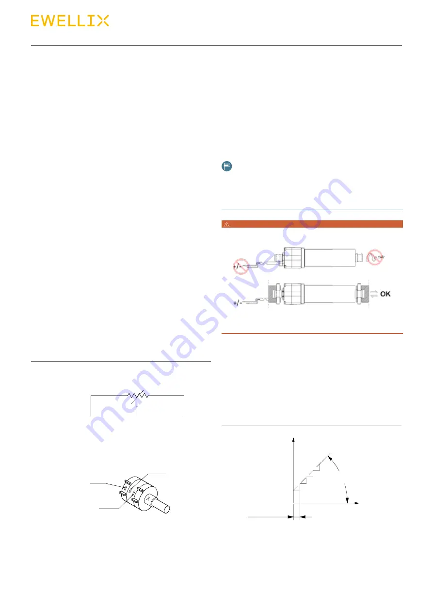
4.6.2 Potentiometer (E design only)
The potentiometer provides a signal indicating the position
of the linear actuator. The electrical specification as on the
datasheet.
• Linear actuator with potentiometer unit: colours of wire are
white, green and brown (⮑ Fig. 15).
Retract
Extend
Green
Brown
White
POT
Limit + POT:
White
Green
Brown
0
CW
10K
Fig. 15
Potentiometer
4.6.3 Absolute analog position output
E design
The absolute analog position sensor is a multitude non-con-
tact magnetic sensor. It provides a signal indicating the posi-
tion of the linear actuator. the output signal is 0 ~ 5V DC volt-
age (current output 5 mA max). The electrical specification
and resolution refer to date sheet, the wires connecting refer
to 6.4.1 Wiring scheme.
NOTE
When actuator with POT or the analog output, don’t rotate the push
tube 45 degree and don’t connect to power before the actuator is
installed into device (see picture below) Otherwise would demage
the potentiometer or the analog sensor components.
WARNING
S design
The absolute analog position output is simulated by smart
PCBA. It provides a signal indicating the position of the lin-
ear actuator. The output signal is 0~5 or 0~10 V DC (current
output 15 mA max) depending of ordering key selection. The
electrical specification and resolution refer to data sheet, the
wires connecting refer to 6.4.3 S design wiring scheme
output (V)
5
4,5
0,5
0
resolution
tan (α) = output relation to
displacement (V/mm)
α
displacement (mm)
Fig. 16


