8.
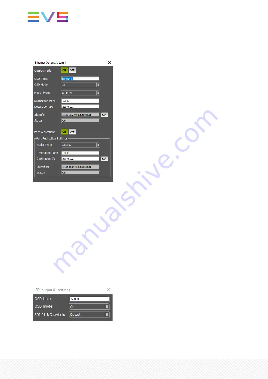
Ethernet output number button. When this button is green, the corresponding output stream status is
ON. Any other status will show a gray button. Clicking this button will open a pop-up with the
Ethernet stream output settings.
Output mode switches the corresponding Ethernet output stream on or off. OSD text and OSD mode
allows you to display on-screen indicators of the stream’s video (e.g. Ethernet 1 stream 7), allowing
you to identify this output on, for instance, a multiview wall. With Media Type you can change the
output format (e.g. S2022-6 or s2110-20). Destination port and IP address set the destination of the
stream. The Identifier can be copy/pasted to other equipment to subscribe to this multicast stream.
You can enable port replication for redundant outputs.
9.
Ethernet output
path assignment. In these drop-down boxes you choose which processing path
should be set to the corresponding Ethernet stream output. This can be any of the paths A1 to D4.
Setting the same path to multiple output streams is possible.
10.
Ethernet link status icon. This icon has the same functionality as the ethernet link status icon
explained above (in 4).
11.
SDI output
number button. This button is either transparent (dark gray), when the output is disabled
or set to INPUT, or not transparent (light gray), when the output is enabled and set to OUTPUT.
Clicking this button will open a pop-up with SDI output settings.
OSD text and OSD mode allows you to display on-screen indicators on the SDI output video (e.g. SDI
output 5) allowing you to identify this output on for instance a multiview wall. The SDI I/O switch
allows you to switch the output OFF (all outputs) or to switch it to INPUT (outputs 9 to 32).
20
| February 2022 | Issue 4.9.C


