


ENVR8304D-8CH / ENVR8304E-8CH
115
6.8.3
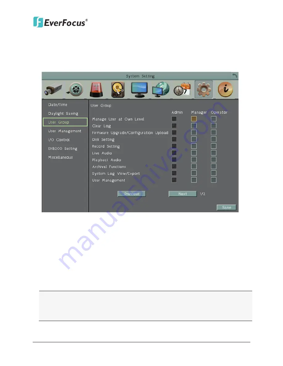
User Group
This setting page is used for configuring the privilege of the three access levels:
Administrator, Manager and Operator. Check the boxes under an access level to enable the
privileges of that access level. For example, if you check the
Clear Log
box under the
Operator access level, only the Operator has the privilege to clear log.
Figure 6-56
Manage User at Own Level:
Check this box for the user of an access level to be able to
configure other users’ settings of the same level at the User Management setting page (see
6.8.4 User Management
). For example, if this box under the Operator level has been
checked, any user with the Operator privilege can go to the User Management setting page
to set up the settings of other Operators.
User Management:
Check this box under an access level to enable the users of that level to
access the User Management and User Group setting page.
Previous:
Click to return to the previous page.
Next:
Click to enter the next page.
Note:
Users with the Administrator account have full privileges, so the checkboxes under
the Administrator access level will always be grayed out. The Administrator can grant
privileges to both the Manager and Operator while the Manager can only give privileges to
the Operator. The Operator has no right to configure this page.


