7
1.5
REAR PANEL
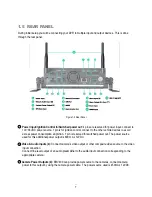
During initial setup you will be connecting your DVR to multiple input and output devices. This is done
through the rear panel.
Figure 1-2 Rear Panel
○
1
Power Input/Ignition Control In/Switched power out: 4 pins are reserved for power input; connect to
10V~36VDC power source. 1 pin is for ignition control; connect to the other vehicle devices to avoid
excess power consumption at ignition. 1 pin is reserved for switched power out. The power source
used for this additional power output is 600 mA x 12VDC.
○
2
Video & Audio Inputs (4): Connect camera’s video output or other composite video source to the video
input connection.
Connect line level output of an audio preamplifier to the audio input connection corresponding to the
appropriate camera.
○
3
Camera Power Outputs (4):
EMV400 can provide power source to the cameras, connect camera
power to this output by using the camera power cable. The power source used is 450mA x 12VDC.
Summary of Contents for EMV400
Page 1: ...User Manual E EM MV V4 40 00 0 D DV VR R ...
Page 42: ...34 Figure 4 2 Configuration Menu ...
Page 96: ...88 ...
Page 97: ...89 ...
Page 106: ...98 Once the file finishes installing you will return to the screen like the one below ...


