Instruction Manual ZHK
V07-19.0
89/129
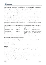
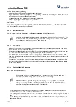
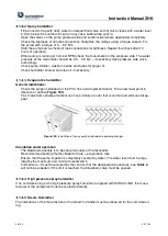
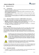
When the differential pressure switch has been activated, the cause of the excessive pressure must
be found and eliminated before restarting.
Value to be set:
The setting of the differential pressure switch must be done on site, based on the actual pressure
situation on site. The actual differential pressures must be measured at the commissioning with the
target volume flows
–
measuring points depending on the fan arrangement can be found in
. From the beginning until reaching the target volume flow, the maximum admis-
sible differential pressure according to the technical data must not be exceeded. Based on these
measured values reserves for, for example, filter pressures losses or other additional pressure
losses must be added. This calculated pressure must be adjusted at the differential pressure switch
as trigger value.
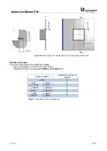
It must be confirmed, that this calculated value does not exceed the maxi-
mum admissible differential pressure according to the technical data, see
Figure 185.
If the maximum admissible differential pressure is not given in the tech-
nical data, EUROCLIMA must be contacted.
If EUROCLIMA supplies the differential pressure switch, then they are factory mounted. The setting,
as described above, must be executed by the customer on site at commissioning. The correct con-
nection of the measuring hoses, according to
, must be ensured before
commissioning.
If you have any questions or doubts regarding the correct installation, connection and adjustment
of differential pressure switches or other measures to protect against impermissible pressures,
please contact EUROCLIMA.
7.8
Frost protection for plate heat exchanger
At low temperatures and high air speeds, the condensate in the plate heat exchanger can freeze
and cause its icing.
For devices supplied by EUROCLIMA with control, this is prevented by pressure monitoring of the
plate heat exchanger and the temporary adjustment of the supply air volume flow. For devices sup-
plied by EUROCLIMA without control, appropriate measures are required to protect the plate heat
exchanger on site. For example, a temporary reduction of the supply air flow.
7.9
Lighting
Depending on the number of delivered (optional) lamps, the assignment of the switches and junction
boxes can be found below:
1 Lamp
1 switch
> 1 <= 4 Lamp
1 switch, 1 junction box
> 4 <= 8 Lamp
1 switch, 2 junction box
> 8 <= 12 Lamp
1 switch, 3 junction box
The lamps are mounted and supplied with one side connected and one side with loose cables, suf-
ficient in length to be routed to the nearest junction box or the next switch.
The AHU will be delivered in parts, and for this reason the lights have to be connected on site and
the client is responsible for the completion of this work.
Summary of Contents for ZHK Series
Page 1: ...ZHK INSTRUCTION MANUAL ...

