


Instruction Manual ZHK
V07-19.0
41/129
-
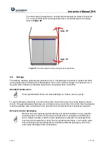
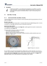
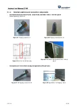
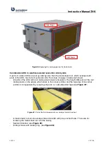
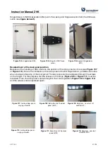
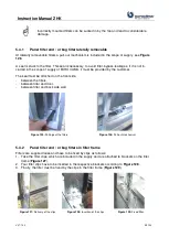
Connection of connection frame and partition walls
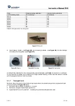
Screw spacing: according holes in the connection frame
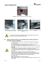
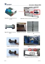
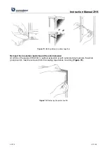
Figure 70: S
elf-tapping screw ø6,3 x
22
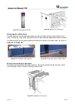
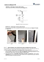
Figure 71:
Connection frame and partition
wall (not screwed yet)
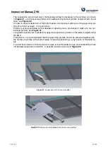
Figure 72:
Screwing of the
parts
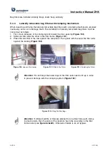
5.1.4
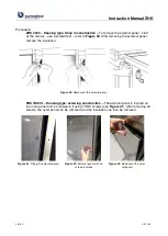
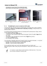
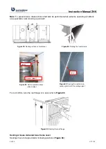
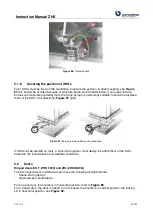
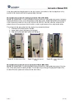
Establishing the screw connection of AHU parts
The exact alignment of the AHU parts and pulling together of the AHU parts as close as possible,
as described in
chapter 5.1.1
Actions before the assembly of casing
), are requirements for es-
tablishing screw connection.
The precisely aligned and parallel flanges are connected with the enclosed bolts. Initially, all bolts
are only loosely screwed as follows:
-
In the base frame profiles (
-
If accessible, in the connection angles located in the upper corners of the AHU (
tom center).
-
If accessible, in the circumferential connection frame (
-
In the panels (
-
For roof AHUs in the roof flange.
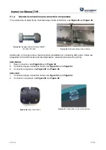
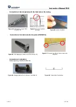
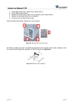
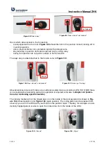
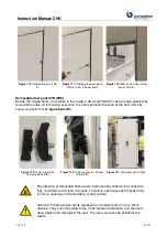
If only one side is accessible (panels and connection frame) the tapping screws ø8 x 11 or Ejot ø8
x 16 shall be used, otherwise bolts and nuts (all supplied separately):
-
Bolts M8 x 20 for connection angles and base frame
-
Bolts M6 x 16 for connection frame and panels
For the tightness at least every second hole (bolt spacing 305 mm) shall be used.
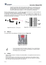
After placing all the screws loosely, they shall be tightened - starting with the base frame
–
in two
stages.
It is important, to tight initially the bolt connection at the base frame. This is to en-
sure an exact connection of the AHU parts.
connection frame
with holes
partition wall
Summary of Contents for ZHK Series
Page 1: ...ZHK INSTRUCTION MANUAL ...