


System Manual Safety System MGB-AR in Combination with a Locking Module
18
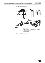
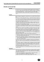
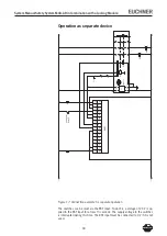
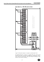
Operation as separate device
Figure 17: Connection example for separate operation
The switches can be reset via the RST input. To do this, a voltage of 4 V is ap-
plied to the RST input for at least seconds. The supply voltage to the switches
is interrupted during this time. The RST input must be connected to 0 V if it is not
used.
24
V
G
N
D
-F
1
X5.
6
UB
X5.
5
0V
X5.
4
OU
T4
X5.
3
OU
T3
X5.
2
OU
T2
X5.
1
OU
T1
X4.
6
RST
M
G
BL
X4.
5
OB
X4.
4
OA
X4.
3
---
X4.
2
IB
X4.
1
IA
En
tr
ie
ge
ln/
Unlock
X3.
7
UC
M
X3.
6
0VM
X3.
5
0VM
-F
2
X3.
4
UA
A1
24
VD
C
A1
A2
S1
1
S1
0
ES
M
-B
A3
xx
S1
3
EU
C
H
N
ER
St
ar
t
KA
KB
S2
1
S1
2
K1
+
S1
4
K2
+
13
14
KA
A1
A2
23
24
KB
A1
A2
33
34
41
42


