


System Manual Safety System MGB-AR in Combination with a Locking Module
14
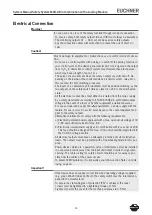
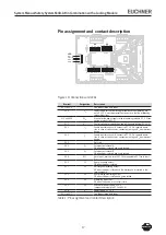
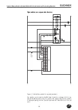
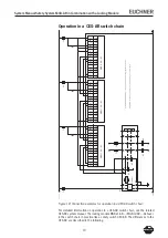
Electrical Connection
Warning!
In case of an error, loss of the safety function through incorrect connection.
To ensure safety, both safety outputs (OA and OB) must always be evaluated.
The monitoring outputs O1 ... O4 must not be used as safety outputs.
Lay the connection cables with protection to prevent the risk of short cir-
cuits.
Caution!
Risk of damage to equipment or malfunctions as a result of incorrect connec-
tion.
Do not use a control system with pulsing or switch off the pulsing function in
your control system. The device generates its own clock signal on the output
lines O
A
/O
B
. A downstream control system must tolerate these test pulses,
which may have a length of up to 1 ms.
The pulses are also present when the safety outputs are switched off. De-
pending on the inertia of the connected device (control system, relay, etc.),
this can lead to short switching processes.
The inputs on an evaluation unit connected must be positive-switching, as the
two outputs on the safety switch deliver a level of +4 V in the switched-on
state.
All the electrical connections must either be isolated from the mains supply
by a safety transformer according to EN IEC 61558--6 with limited output
voltage in the event of a fault, or by other equivalent isolation measures.
For use and operation as per the
requirements, a power supply with the
feature "for use in class circuits" must be used. The same requirement ap-
plies to the safety outputs.
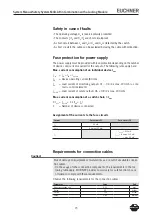
Alternative solutions must comply with the following requirements:
a) Electrically isolated power supply unit with a max. open-circuit voltage of 0
V/DC and a limited current of max. 8 A.
b) Electrically isolated power supply unit in combination with fuse as per UL48.
This fuse should be designed for max. . A and should be integrated into
the 0 V/DC voltage section.
All electrical outputs must have an adequate protective circuit for inductive
loads. The outputs must be protected with a free-wheeling diode for this pur-
pose.
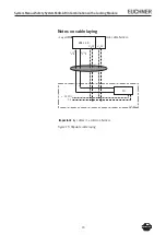
Power devices which are a powerful source of interference must be installed
in a separate location away from the input and output circuits for signal pro-
cessing. The cable routing for safety circuits should be as far away as pos-
sible from the cables of the power circuits.
To prevent EMC problems, it is imperative you follow section
Notes on cable
laying
, page 16.
Important!
If the device does not appear to function when operating voltage is applied
(e.g. green DIA LED does not flash), the safety switch must be returned uno-
pened to the manufacturer.
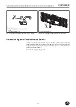
To ensure the stated degree of protection IP67 is achieved, the cover
screws must be tightened to a tightening torque of 1 Nm.
Tighten screw for the cover for the mechanical release to 0.5 Nm.


