


System Manual Safety System MGB-AR in Combination with a Locking Module
15
Safety in case of faults
The operating voltage U
B
is reverse polarity protected.
The contacts I
A
/I
B
and O
A
/O
B
are short circuit-proof
A short-circuit between I
A
and I
B
or O
A
and O
B
is detected by the switch.
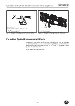
A short circuit in the cable can be excluded by laying the cable with protection.
Fuse protection for power supply
The power supply must be provided with fuse protection depending on the number
of devices and current required for the outputs. The following rules apply here:
Max. current consumption of an individual device I
max
I
max
= I
UB
+ I
UA
+ I
OA+OB
I
UB
= Device operating current (80 mA)
I
UA
= Load current of monitoring outputs O1 ... O4 (4 x max. 00 mA) + sole-
noid + control elements
I
OA+OB
= Load current of safety outputs OA + OB ( x max. 00 mA)
Max. current consumption of a switch chain
Σ
I
max
Σ
I
max
= I
OA+OB
+ n x (I
UB
+ I
UA
)
n
= Number of devices connected
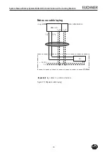
Assignment of the currents to the fuse circuits
Current
Fuse circuit F1
Fuse circuit F2
I
UB
80 mA
I
OA+OB
( x max. 00 mA)
I
UA
I
Solenoid
= 50 mA
I
O1...O4
= (4 x max. 00 mA)
I
Control elements
= max. 0 mA
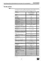
Requirements for connection cables
Caution!
Risk of damage to equipment or malfunctions as a result of unsuitable connec-
tion cables.
On the usage of other connection components, the requirements in the fol-
lowing table apply. EUCHNER provides no warranty for safe function in case
of failure to comply with these requirements.
Observe the following requirements for the connection cables:
Parameter
Value
Unit
Wire cross-section min.
0,1
mm²
R max.
60
W
/km
C max.
10
nF/km
L max.
0,65
mH/km


