


MAINTENANCE
48
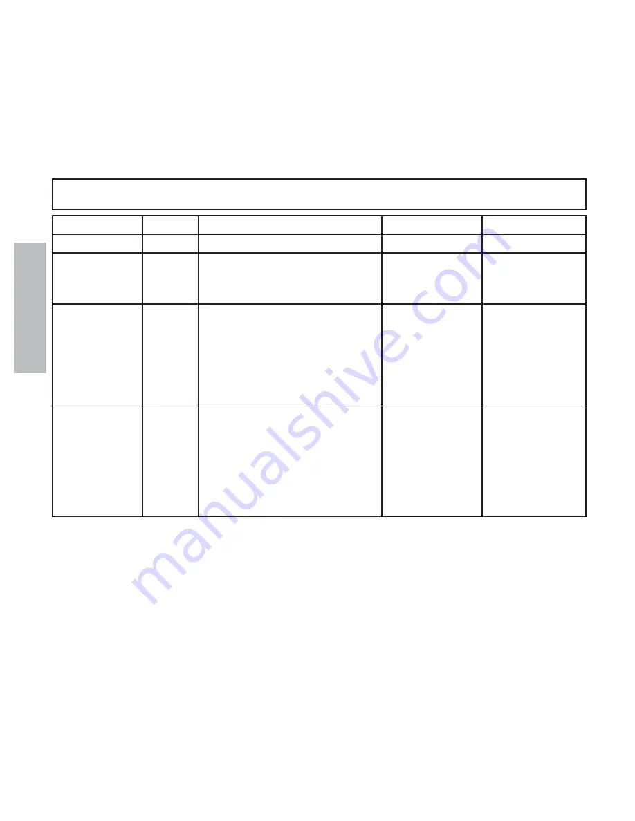
INTERVAL
POINT
IDENTIFICATION
LUBRICANT
QUANTITY
DAILY
1
Pump Discharge Strainer
Clean
WEEKLY
2
Air Oiler
EO
Fill
3
Manhole Cover
EO
Sparingly
4
Spray Bar Controls
AS
Sparingly
30 DAYS
5
4-way Valve Handle
MPG
Sparingly
6
Bar Swivels
MPG
Sparingly
7
Bar Carry Mechanism
EO
Sparingly
8
Mechanism Swivels
MPG
Sparingly
9
Mechanism Pivot Bar Ends
MPG
Sparingly
10
Mechanism Cylinders
MPG
Sparingly
SERVICE
11
Bell Crank
AS
Sparingly
12
PUMP SHAFT
AS
Sparingly
13
Bar Balls
MPG
Sparingly
14
Hydraulic Reservoir
HTF
3/4 Full
15
Hydraulic Oil Filter
Replace if
Vacuum shows
in the red area
MPG: Multi Purpose Grease MIL-G-18458B-SH
EO: (Engine Oil) 10W MIL-L-2104-F
AS: Anti-Seize MIL-T-5544
HTF: Hydraulic Transmission Fluid - Type F
NOTE: Fill line oiler, located on outlet side of air reservoir, with light oil as needed. Also wipe cylinder rods clean and lightly
oil. Drain water from air reservoir daily.
NOTE: Fill Hydraulic Tank completely for winter storage. This will prevent condensation in the reservoir. Drain down to
thermometer hole prior to use.
Lubrication Chart
cuit systems, and closed systems with cylinders being
supplied from the same reservoir, a considerably higher
filter efficiency is recommended. This applies to sys-
tems with gears or clutches using a common reservoir.
For these systems, Beta ratios of 10 or 20 are typically
required.
The filter capacity required depends on the amount
of contaminants ingressed and retained in the filter and
the desired maintenance interval. As a rough guide, a
capacity in grams equal to twice the charge flow in GPM
has been found to be satisfactory for our systems.
Since each system is unique, the filtration require-
ments for that system will be unique and must be deter-
mined by test in each case. It is essential that monitor-
ing be the final criteria for judging the adequacy of the
filtration system.