background image

W

ATLOW

®


EZ-ZONE

®


RMZ4


-


27


E

THER

CAT

® 

A

DAPTER 


8


U

SING 

C

ONTROLLER 

F

EATURES 


8.1


S

ENSOR AND 

C

ONTROL 

L

OOP 


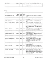
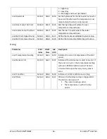
Mapping 

Parameter 

ECAT 

Index 

DNET 

Class 

Sub 

/Attr 

Description 

Loop Location 

0x4nn0  0x67 

0x11 

I

ndicates if the loop is hosted locally (0) or 

remotely (1). If the sensor is mapped to the RM 
bus or optical inputs or Remote PV then loops are 
locally executed in the RMZ4 modules. If the 
sensors are in the ST, PM, SL-10, or CLS then the 
loops are remote since those devices are fully 
integrated controllers. 

Sensor Bus 

0x4nn0  0x67 

0x12  Defines the bus the loop uses for the control 

sensor. 
0 = Unused 
1 = RM 
2 = Legacy ST/PM 
3 = Modbus 
4 = Internal Optical Sensor Card 
5 = Remote PV from 0x3000:0x13 

Sensor Zone 

0x4nn0  0x67 

0x13  Defines which zone or address that is hosting this 

sensor input. For EZ-ZONE products it is the zone 
number displayed on the front. For EHG SL-10 it is 
the Modbus address. Optical sensors 1-4 are local 
in the RMZ4 so this value does not have meaning. 
Independent RMF optical modules are considered 
sensor type 1 – on the backplane. 

Sensor Instance 

0x4nn0  0x67 

0x14  Defines which sensor instance on a particular zone 

for devices that have multiple inputs. For instance, 
an RMS module can have 16 TC inputs.  
To map to sensor 5 on RMS zone 3: 

Select Bus 2, Zone 3, Instance 5. 


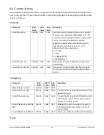
Configuring Sensor 

Parameter 

ECAT 

Index 

DNET 

Class 

Sub 

/Attr 

Description 

Sensor Type 

0x8nn0 

0x6D 

0x11 

Sets the input type to  
0 = TC  
1 = RTD100  

Summary of Contents for EZ-ZONE RMZ4

Page 1: ...Z ZONE RMZ4 1 ETHERCAT ADAPTER EZ ZONE RMZ4 EtherCAT User s Guide Adapter 0600 0103 0000 Revision A 7 1241 Bundy Boulevard Winona Minnesota USA 55987 Phone 1 507 454 5300 Fax 1 507 452 4507 http www watlow com ...

Page 2: ...therCAT Master and ESI file 20 7 3 Master instructions 20 7 4 Explicit Device Identification 20 7 5 Mapping Loop to CoE Object Indexes 21 7 6 Configuring the RMZ4 22 7 7 Identifying the RMZ4 Itself 22 7 8 Setting Addresses on Connected Devices 22 7 9 Identifying Connected Devices 22 7 10 Adding Slots 25 7 11 Mapping I O to Loops Slots 26 8 Using Controller Features 27 8 1 Sensor and Control Loop 2...

Page 3: ...ser RxPDO 58 10 6 User TxPDO 58 11 Control Operation 66 11 1 Network State and Control States 66 11 2 Data Retention 66 11 3 Control Loops 66 11 4 Alarms 66 12 Additional Connectivity 67 12 1 Bluetooth 67 12 2 Modbus Slave 67 12 3 Modbus Master 67 13 Flash Loading 67 13 1 Over EtherCAT 67 13 2 Over USB 67 14 Supporting Documents and Files 68 15 Troubleshooting Guide 69 16 RMZ4 Specifications 70 17...

Page 4: ...on for shock hazard prevention Functional earth ground connection may be present Do not throw in trash use proper recycling techniques or consult manufacturer for proper disposal Enclosure made of Polycarbonate material Use proper recycling tech niques or consult manufacturer for proper disposal Unit can be powered with either alternating current ac or direct current dc Unit is a Listed device per...

Page 5: ... host a legacy communications adder card This card provides additional connection points for Modbus DeviceNet and Watlow Standard Bus These cards are intended to extend the network beyond RM modules to include displays like Watlow Silver Series and EZ ZONE EZK and legacy controllers such as the EHG SL 10 The Watlow EZ ZONE ST and EZ ZONE PM may be integrated from the C connector without requiring ...

Page 6: ...WATLOW EZ ZONE RMZ4 6 ETHERCAT ADAPTER 4 MOUNTING AND DIMENSIONS FIGURE 1 DIMENSIONS Recommended chassis mounting hardware 1 8 screw Long 2 Torque to 10 15 in lb 3 No washers ...

Page 7: ... AND WIRING 5 1 RMZ4 WITH UP TO 48 CONTROL LOOPS FIGURE 2 CONNECTIONS POINTS FOR RMZ4 __AA AAAA RM Module Bus Backplane Explicit Device ID Switches EtherCAT IN EtherCAT OUT USB Configuration Port for PC EtherCAT status LEDs Slot C Power and Standard Bus ...

Page 8: ... optical sensing is defined in the model number xxxx xx04 xxxx The fluorescent probes are available from Watlow The range is generally 100 to 200C without special probe construction Each probe is connected via a bayonet style ST connectors To use this input in a control loop define the bus as Optical option 4 and select instance 1 2 3 or 4 RM Module Bus Backplane Explicit Device ID Switches EtherC...

Page 9: ...11AA WITH SERIAL COMMS CARD AND BLUETOOTH RM Module Bus Backplane Explicit Device ID Switches EtherCAT IN EtherCAT OUT USB Configuration Port for PC EtherCAT status LEDs Slot C Power and Standard Bus Connection to Modbus slave devices Connection to HMI Modbus Master Extra Standard Bus Connection Bluetooth Connection to Tablet Phone PC ...

Page 10: ...dard Bus Connection Explicit Device ID Switches EtherCAT IN EtherCAT OUT USB Configuration Port for PC EtherCAT status LEDs Slot C Power and Standard Bus Connection to HMI Modbus Master DeviceNet Address Switches Bluetooth Connection to Tablet Phone PC DeviceNet Speed Switch Extra Standard Bus Connection ...

Page 11: ... the figure Notice in the split rail system diagram that a single power supply is used across both DIN rails One notable consideration when designing the hardware layout would be the available power supplied and the loading effect of all of the modules used Watlow provides three options for power supplies listed below 1 90 264VAC to 24VDC 31 watts Part 0847 0299 0000 2 90 264VAC to 24VDC 60 watts ...

Page 12: ...tion 98 99 Power Input AC or DC Power Input AC or DC Only needed on one module shared on backplane CF CD CE Standard Bus EIA 485 Common Standard Bus EIA 485 T R A Standard Bus EIA 485 T T B EIA 485 connection for EZ ZONE Configurator CZ CX CY Inter module Bus Inter module Bus Inter module Bus Wire for Split Rail Configurations ...

Page 13: ...t a ground wire into either of the traps as viewed from the case bottom The ETG 5003 Semi Standard recommends grounding the jacket Each jacket is connected to the terminal trap via a 50ohm resistor This earth ground is not connected to the power FIGURE 5 GROUND WIRE LOCATION FIGURE 6 GROUND WIRE INSERTION Use 18 26 AWG Solid or Stranded Trim Length 3 5 0 5mm 0 138 02 Twist wire to remove ...

Page 14: ...WIRING Connect EZ ZONE STs or PMs via the CF Com CD A and CE B terminals on the Slot C connector This is the RS 485 Standard Bus connection The RMZ4 will recognize these devices automatically View and confirm discovered devices using the 0xF500 objects 5 10 DEVICE WIRING ...

Page 15: ...c or Compare blocks Use the EZ ZONE Configurator software to connect via the USB port All the RM devices in the system should appear when the network is scanned Use the Watlow_USB inf driver located on watlow com to create a USB serial port on your PC 5 14 MODBUS RTU RS 485 WIRING RJ 12 MASTER OR SLAVE If the RMZ4 has the optional Legacy Communications card it can be connected to simple Modbus tem...

Page 16: ...WATLOW EZ ZONE RMZ4 16 ETHERCAT ADAPTER FIGURE 7 MODBUS MASTER AND SLAVE RJ 12 CONNECTOR PINOUT ...

Page 17: ... 5 to 4ms typically The data in the PDO is a selected set of Object SubIndex parameters Typical PDO parameters are process temperature set point output power and errors PDO data is only exchanged when the system is in the operational mode OP mode As a default the RMZ4 controller only controls temperature in the operational mode The Safe State parameter configures this behavior SDO is Service Data ...

Page 18: ...ange The configuration values changed will take effect within 200ms The RMZ4 models individual control loops as modules or slots as described by the EtherCAT Modular Device Profile Each control loop is mapped to a module or slot This is a logical association The EtherCAT loop module does not map one to one with physical RM modules The configuration section describes how to map the I O in each RM p...

Page 19: ...WATLOW EZ ZONE RMZ4 19 ETHERCAT ADAPTER FIGURE 9 RM CONTROL LOOP TOPOLOGY FIGURE 10 COMPLETE NETWORK INTERACTION DIAGRAM ...

Page 20: ... bit Windows PC The Master needs an ESI file to describe the device and its capabilities This file is in XML format and provided by Watlow for the RMZ The ESI file contains the object dictionary for the RMZ There is one ESI file regardless of the version of RMZ that contains the parameter details for all product versions The master will select the correct version from the ESI based on the version ...

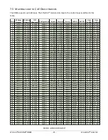
Page 21: ...28 0x1A28 0x1629 0x1A29 22 0x2150 0x3150 0x4150 0x4151 0x6150 0x7150 0x8150 0x162A 0x1A2A 0x162B 0x1A2B 23 0x2160 0x3160 0x4160 0x4161 0x6160 0x7160 0x8160 0x162C 0x1A2C 0x162D 0x1A2D 24 0x2170 0x3170 0x4170 0x4171 0x6170 0x7170 0x8170 0x162E 0x1A2E 0x162F 0x1A2F 25 0x2180 0x3180 0x4180 0x4181 0x6180 0x7180 0x8180 0x1630 0x1A30 0x1631 0x1A31 26 0x2190 0x3190 0x4190 0x4191 0x6190 0x7190 0x8190 0x16...

Page 22: ...ce to these stand alone controllers The data is presented to the network with the same model 7 7 IDENTIFYING THE RMZ4 ITSELF The identity of the RMZ4 module is accessed through objects 0x1000 7 8 SETTING ADDRESSES ON CONNECTED DEVICES Each EZ ZONE RMS RME RML RMF RMC or RMH device needs a unique address to identify it on the bus This is the orange digit in the upper right hand side of the device T...

Page 23: ...WATLOW EZ ZONE RMZ4 23 ETHERCAT ADAPTER ...

Page 24: ...WATLOW EZ ZONE RMZ4 24 ETHERCAT ADAPTER ...

Page 25: ...odules or EZ ZONE ST or PM Typically a system will use and RMS for input and an RME for outputs and current transformers This system can be augmented with an RML limits module for over temp protection If the system has few loops an RMC is an option for integrating sensor outputs limits and CT is one hardware module The 0x4000 objects are used to define the I O location for each loop The maximum nu...

Page 26: ...6 Digital outputs map to zone 2 DIO instance 1 to 16 This may not match your system Make sure to verify all mapping points and set unmapped elements to bus 0 unused to ensure proper operation Send the Save Non Volatile Command to ensure the mapping is maintained Bus Designators Bus Bus Loop Location Sensor Outputs Current Limits 0 None Not Active Yes Yes Yes Yes 1 RM Backplane Split Rail Internal ...

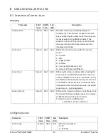
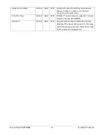
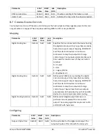
Page 27: ...PM 3 Modbus 4 Internal Optical Sensor Card 5 Remote PV from 0x3000 0x13 Sensor Zone 0x4nn0 0x67 0x13 Defines which zone or address that is hosting this sensor input For EZ ZONE products it is the zone number displayed on the front For EHG SL 10 it is the Modbus address Optical sensors 1 4 are local in the RMZ4 so this value does not have meaning Independent RMF optical modules are considered senso...

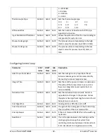
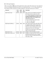
Page 28: ... heat gain as a proportional band Increase reduces gain and increases stability Decreasing increases responsiveness Integral Time 0x8nn0 0x6D 0x27 Sets the rate the power increases or decreases This will pull the temperature to set point A low value integrates power quickly but can cause instability Derivative Time 0x8nn0 0x6D 0x28 Sets the derivative time constant Reacts in opposition to changes ...

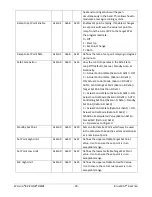
Page 29: ...O Controlling Set Point 0x6nnn SI 0x16 Target Set Point 0x7nnn SI 0x11 2 Actual Control State 0x6nnn SI 0x01 ON Actual Control Mode 0x6nnn SI 0x02 AUTO Controlling Set Point 0x6nnn SI 0x16 Standby Set Point 0x8nnn SI 0x20 3 Actual Control State 0x6nnn SI 0x01 ON Actual Control Mode 0x6nnn SI 0x02 MANUAL Manipulated Value 0x6nnn 0x12 Forced MV 0x7nnn SI 0x12 4 Operate as configured Standby Set Poin...

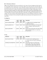
Page 30: ...et point ramping is enabled Manipulated Value 0x6nn0 0x6B 0x12 The output of the control loop which manipulates the heater Heat Manipulated Value 0x6nn0 0x6B 0x13 The positive portion of the Manipulated Value which routes to heat outputs Cool Manipulated Value 0x6nn0 0x6B 0x14 The negative portion of the Manipulated Value which routes to cool outputs Forced Manipulated Value 0x7nn0 0x6C 0x12 This ...

Page 31: ...rror the loop cannot be in the Auto mode Tune Occurring 0x6nn0 0x6B 0x04 Indicates if an auto tune is in progress Tuning is started using command 0xFB30 Remote PV 0x3nn0 0x66 0x13 An external value may be used as the Process Variable If the Sensor Map is set to 5 This value will be the process value and should be provided by the master in an Output PDO ...

Page 32: ...eParameters command and cycle power to the unit The probe curve is only loaded on power up 0 Type 0 is the Watlow standard probe 1 Type 1 is a legacy probe 2 Type 2 is customizable Optical Sensor Warning 0x4nn1 0x68 0x2E Sets a warning point for the probe LED current The default is 15mA When the LED current exceeds this level the status indicator on the front on the module will flash green and red...

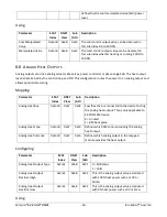
Page 33: ...ld normally change 20 degrees per minute at 100 power the feature could be set to 5 degrees in 60 seconds This would trip if the measured process value does not change at less than its normal rate Configuring Parameter ECAT Index DNET Class Sub Attr Description Open Loop Detect Enable 0x4nn1 0x68 0x2F 1 Enables the Open Loop Detect Feature 0 Disables the feature Open Loop Detect Time 0x4nn1 0x68 0...

Page 34: ...fines which RM zone is providing the digital heat control output Only loops that are locally hosted can support output mapping EZ ZONE ST and PM EHG SL 10 devices do not have a mechanism to map their outputs to foreign control loops They will use their own outputs automatically Digital Heat Instance 0x4nn0 0x67 0x17 Defines which digital output instance on a particular zone implement the control o...

Page 35: ...tion is located Over temp control has dedicated trip circuitry This extra sensor is read at 0 2000 14 for verification The limit is parameterized in the RMZ4 with trip points that are routed to the appropriate RML RMC ST or PM module The limit function and output are independently controlled by the limit module but parameterized through the RMZ 0 Unused 1 RM 2 Legacy ST PM 3 Modbus SL 10 Limit Zon...

Page 36: ...able trip point value Limit Set Point Lower Bound 0x4nn1 0x68 0x18 Define the minimum settable trip point value Using Parameter ECAT Index DNET Class Sub Attr Description Limit Temperature Reading 0x2nn0 0x65 0x14 Indicates the current temperature of the limit sensor Limit Sensor Error 0x2nn0 0x65 0x01 Indicates if the limit sensor is valid or in error If the sensor is in error the temperature rea...

Page 37: ...nused 1 RM 2 Legacy ST PM 3 Modbus SL 10 Current Sense Zone 0x4nn0 0x67 0x1F Defines which zone is hosting the current sense functionality Current Sense Instance 0x4nn0 0x67 0x20 Defines which current sense instance belongs to this loop in a module that hosts multiple current sensors Configuring Parameter ECAT Index DNET Class Sub Attr Description Heater Failure Function 0x4nn1 0x68 0x19 Current T...

Page 38: ...puts to foreign control loops Cool outputs parameters like cycle time need this location even if they are hosted remotely 0 Unused 1 RM 2 Legacy ST PM 3 Modbus SL 10 Digital Cooling Zone 0x4nn0 0x67 0x29 Defines which RM zone is providing the digital cool control output Only loops that are locally hosted can support output mapping EZ ZONE ST and PM EHG SL 10 devices do not have a mechanism to map ...

Page 39: ...appropriate scaling Mapping Parameter ECAT Index DNET Class Sub Attr Description Analog Heat Bus 0x4nn0 0x67 0x18 Specifies the bus connected to the device hosting the analog heat output This is only applicable to EZ ZONE RM device 0 Unused 1 RM back plane Analog Heat Zone 0x4nn0 0x67 0x19 Defines which RM zone is providing the analog heat output Analog Heat Instance 0x4nn0 0x67 0x1A Defines which...

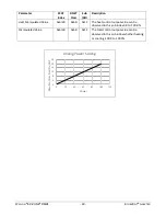
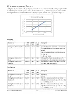
Page 40: ... 0x6B 0x13 The heat control output value can be observed in this sub index 0 0 to 100 0 Manipulated Value 0x6nn0 0x6B 0x12 The total control output value can be observed in this sub index whether heating or cooling 100 0 to 100 0 0 4 8 12 16 20 24 0 20 40 60 80 100 120 Resultant Electrical Ouptut Power Analog Power Scaling ...

Page 41: ...e 0 Unused 1 RM back plane Analog Heat Retransmit Zone 0x4nn0 0x67 0x19 Defines which device zone address on the bus is providing the analog retransmit output Analog Heat Retransmit Instance 0x4nn0 0x67 0x1A Defines which output in this device provides the analog retransmit output Configuring Parameter ECAT Index DNET Class Sub Attr Description Analog Retransmit Output Type 0x4nn1 0x68 0x28 0 Mill...

Page 42: ...m 1 Zone 0x4nn0 0x67 0x2C Defines which device zone address on the bus provides the process alarm 1 Process Alarm 1 Instance 0x4nn0 0x67 0x2D Defines which output in this device provides the process alarm 1 output Mapping Deviation Alarm 2 Parameter ECAT Index DNET Class Sub Attr Description Deviation Alarm 2 Bus 0x4nn0 0x67 0x2E Specifies the communication bus connects to the outputs for the devi...

Page 43: ... 2 High Set Point 0x8nn0 0x6D 0x30 The point where a high alarm 2 becomes active This is a temperature relative to this loops set point typically a positive number like 20C Alarm 2 Low Set Point 0x8nn0 0x6D 0x31 The point where a low alarm 2 becomes active This is a temperature relative to this loops set point typically a negative number like 20C Alarm 2 Set Point Upper Bound 0x8nn0 0x6D 0x32 Alar...

Page 44: ...ides the analog cooling output Analog Cool Output Instance 0x4nn0 0x67 0x34 Defines which output in this device provides the analog cooling output Configuring Parameter ECAT Index DNET Class Sub Attr Description Analog Cool Output Type 0x4nn1 0x68 0x25 0 Milliamps 1 Volts Analog Cool Output Electrical High 0x4nn1 0x68 0x26 This is the analog output value associated with 100 cool power such as 10V ...

Page 45: ...at connects to the module containing direct digital input This is only applicable to EZ ZONE RM device 0 Unused 1 RM back plane Direct Digital Input Zone 0x4nn0 0x67 0x36 Defines which device zone address on the bus provides the direct digital input Direct Digital Input Instance 0x4nn0 0x67 0x37 Defines which output in this device provides the direct digital input Using Parameter ECAT Index DNET C...

Page 46: ...ifies the communication bus that connects to module containing the direct digital output This is only applicable to EZ ZONE RM device 0 Unused 1 RM back plane Direct Digital Output Zone 0x4nn0 0x67 0x39 Defines which device zone address on the bus provides the direct digital output Direct Digital Output Instance 0x4nn0 0x67 0x3A Defines which output in this device provides the direct digital outpu...

Page 47: ...efines which device zone address on the bus provides the analog input Direct Analog Input Instance 0x4nn0 0x67 0x3D Defines which input in this device provides the analog input Configuring Parameter ECAT Index DNET Class Sub Attr Description Direct Analog Input Sensor Type 0x4nn1 0x68 0x32 This is the sensor type for the direct digital input 0 TC 1 RTD100 2 RTD1000 3 4 20mA 4 0 20mA 5 0 10V Direct...

Page 48: ...us connects to the analog outputs for the cooling action This is only applicable to EZ ZONE RM device 0 Unused 1 RM back plane Direct Analog Output Zone 0x4nn0 0x67 0x3F Defines which device zone address on the bus provides the analog cooling output Direct Analog Output Instance 0x4nn0 0x67 0x40 Defines which output in this device provides the analog cooling output Configuring Parameter ECAT Index...

Page 49: ... the group the group will be FALSE 1 If any alarm is condition matches the pick for the group the group will be TRUE Alarm Group 1 Output Bus 0x5F00 0x69 0x12 Defines which bus hosts the digital alarm group 1 output This is only applicable to EZ ZONE RM device 0 Unused 1 RM back plane Alarm Group 1 Output Zone 0x5F00 0x69 0x13 Defines which zone on the bus hosts the digital alarm group 1 output Al...

Page 50: ...fines which zone on the bus hosts the alarm group 5 output Alarm Group 5 Output Instance 0x5F00 0x69 0x24 Defines which output in the zone implements the digital alarm group 5 output Alarm Group 6 Logic 0x5F00 0x25 0x25 Specifies the logic setting for alarm group 6 Alarm Group 6 Output Bus 0x5F00 0x26 0x26 Defines which bus hosts the alarm group 6 output This is only applicable to EZ ZONE RM devic...

Page 51: ...ate the group 5 A process AND a deviation alarm with activate the group 6 A process OR a deviation alarm will activate the group 0x5F01 0x6A 0x02 Determines how alarms from loop 2 map into group 1 For each loop 0x5F01 0x6A 0x30 Determines how alarms from loop 48 map into group 1 Alarm Group 2 Pick List 0x5F02 0x6A 0x01 0x30 Determines how alarms from loop nn map into group 2 Alarm Group 3 Pick Lis...

Page 52: ...utput value for alarm group 2 True or False Alarm Group 3 Value 0x5F00 0x69 0x02 The output value for alarm group 3 True or False Alarm Group 4 Value 0x5F00 0x69 0x02 The output value for alarm group 4 True or False Alarm Group 5 Value 0x5F00 0x69 0x02 The output value for alarm group 5 True or False Alarm Group 6 Value 0x5F00 0x69 0x02 The output value for alarm group 6 True or False Alarm Group ...

Page 53: ...WATLOW EZ ZONE RMZ4 53 ETHERCAT ADAPTER FIGURE 12 ALARM GROUP EXAMPLE ...

Page 54: ...ns to the Safe State to prevent undesired cool downs if desired The Target Set Point Control Mode and Control State are by default provided by the Output PDOs once the system entered the operational mode The must be set using the PDOs then the device is in operational mode 9 3 TUNING Tuning is a process that sets the PID values for a control loop automatically using a standard Zielger Nichols algo...

Page 55: ...r Yes 0x3000 Watlow Specific Output Data SP Desired States Yes 0x4000 Watlow Specific I O Mapping TC Types Ranges Alarm Points Yes 0x4001 Watlow Specific Configuration Cooling Limits and CT parameters Yes 0x5F00 Alarm Grouping Aggregates Alarms No 0x6000 Input Data PV Errors Actual States Current Yes 0x7000 Output Data SP Desired States Yes 0x8000 Configuration Parameters TC Types Ranges Alarm Poi...

Page 56: ... all loops 0xFB31 Cancel a tune The command is a list of loops as string Example 2 5 10 will stop tuning loops 2 5 and 10 Zero will stop tune on all zones Example 0 will stop tuning on all loops Additional method for version 2 0 or later The command is an array of bytes for the loops to stop Example 0x02050A will stop tuning loops 2 5 and 10 Zero will stop tune on all zones Example 0x00 will stop ...

Page 57: ...be lost on power cycle 0x65766173 causes the parameters to be stored A status of 0 means no action A status of 100 means in progress A status of 200 means complete 0xFBF3 Calculate Parameter Checksum s The command is a byte Writing 0x01 will cause the checksum recalculation of all 0x4000 and 0x8000 parameters A status of 0 means no action A status of 100 means in progress A status of 200 means com...

Page 58: ...mitted by the controller every scan cycle usually 1 10ms as controlled by the master Is it configured at index 0x1A00 for loop1 0x1A02 for loop2 etc PDO Sub Index Name PDO Entry Index PDO Entry Sub Index PDO Entry Name 0x01 Sub Index 001 0x6nn0 0x11 Process Value Loop nn 0x02 Sub Index 002 0x6nn0 0x17 Alarm Condition Loop nn 0x03 Sub Index 003 0x6nn0 0x12 Manipulated Value Control Output Loop nn 0...

Page 59: ...reads and writes will match the EtherCAT SDO CoE with the class translation from the table above See the EtherCAT ETG 5003 2060 Object Dictionary for the complete set of attributes Sub Indexes per class 11 2 O T DEVICENET IMPLICIT SETUP CLASS 0X70 The implicit O T data has fixed elements and user elements configured in class 0x70 The fixed elements are the same as the EtherCAT RxPDO These are syst...

Page 60: ... N 3 Per Parameter Value of User 0x70 N 4 Per Parameter Value of User 0x70 N 5 Per Parameter Value of User 0x70 N 6 Per Parameter Value of User 0x70 N 7 Per Parameter Value of User 0x70 N 8 Per Parameter Value of User 0x70 N 9 Per Parameter Value of User 0x70 N A Per Parameter 11 4 FIXED O T DEVICENET ENTRIES The fixed elements same as RxPDO 0x1600 will appear in the implicit data ahead of the use...

Page 61: ...le Alignment Padding 8 N bits Loop 2 Value of Set Point 2 32 Clear Alarm Word 2 16 Value of Forced MV Value 2 32 Loop Control Mode 2 1 Loop Control State 2 1 Alignment Padding 14 Value of User 0x70 2 1 Per Parameter if configured Value of User 0x70 2 2 Per Parameter if configured Value of User 0x70 2 A Per Parameter if configured Possible Alignment Padding 8 N bits Loop 3 Value of Set Point 3 32 C...

Page 62: ...WATLOW EZ ZONE RMZ4 62 ETHERCAT ADAPTER Value of User 0x70 N 2 Per Parameter if configured Value of User 0x70 N A Per Parameter if configured Possible Alignment Padding 8 N bits ...

Page 63: ...ser 0x71 N 2 Class ID Attribute ID User 0x71 N 3 Class ID Attribute ID User 0x71 N 4 Class ID Attribute ID User 0x71 N 5 Class ID Attribute ID User 0x71 N 6 Class ID Attribute ID User 0x71 N 7 Class ID Attribute ID User 0x71 N 8 Class ID Attribute ID User 0x71 N 9 Class ID Attribute ID User 0x71 N A Class ID Attribute ID 11 7 T O DEVICENET IMPLICIT READ BACK CLASS 0X73 The values for these entries...

Page 64: ...32 Alarm Condition 1 16 Manipulated Value 1 32 Controlling Set Point 1 32 Actual Loop Control State 1 1 Sensor Error 1 1 Actual Loop Control Mode 1 1 Alignment Padding 13 Value of User 0x71 1 1 Per Parameter if configured Value of User 0x71 1 2 Per Parameter if configured Value of User 0x71 1 A Per Parameter if configured Possible Alignment Padding 8 N bits Loop 2 Process Value 2 32 Alarm Conditio...

Page 65: ... Parameter if configured Possible Alignment Padding 8 N bits Loop N Process Value N 32 Alarm Condition N 16 Manipulated Value N 32 Controlling Set Point N 32 Actual Loop Control State N 1 Sensor Error N 1 Actual Loop Control Mode N 1 Alignment Padding 13 Value of User 0x71 N 1 Per Parameter if configured Value of User 0x71 N 2 Per Parameter if configured Value of User 0x71 N A Per Parameter if con...

Page 66: ...ster must issue an explicit store of parameters to non volatile memory command It does not occur implicitly behind the scenes To cause the configuration parameters to be stored to non volatile memory the master needs to write to Command 0xFBF2 with 0x65766173 to cause the parameters to be stored The advantage of storing in non volatile is the system I O will be configured properly at power up befo...

Page 67: ...9224 13 2 MODBUS SLAVE The 2000 3000 4001 6000 7000 8000 indexes map into the 6000 and 7000 banks of Modbus registers with each control loop instance having an offset of 50 The primary purpose is to support HMI user interfaces that are Modbus masters 13 3 MODBUS MASTER Not implemented in release 1 This will collect data from modus slave devices and present it in the EtherCAT data model allowing co...

Page 68: ...mage to send to the device over EtherCAT ObjectDictionary_ETG5003_2060_Watlow_A xlsx Specifies all EtherCAT objects for the adapter RMZ_ModbusMap xlsx Defines the object dictionary mapped to Modbus Registers This is accessible over the RJ 12 Modbus Slave Jack This is a convenient point for connecting a Watlow Silver Series HMI This interface is set to 38400 baud 8 data bits 1stop bit No Parity at ...

Page 69: ...nput must be between the Over Temp and Under Temp points The limit function must be Both Sides High or Low The limit condition 0x6nnn 0x18 must be 0 clear Clear the limit by writing to 0x3nnn 0x11 Heater Current sense does not report values Verify the current sense is mapped in 0x4nn0 The Current sense must be on the same loop as the control output and in the same RM module The output must be cond...

Page 70: ... RML RMC ST module CE Weight 200 grams 7 oz without adder cards Wiring Slot C connector Touch safe removable 12 to 30 AWG Torque 0 8 N m 7 0 lb in right angle Mounting DIN rail spec EN50022 35x7 5mm Control Loops 48 max set by model number Process Alarms 1 per control loop Deviation Alarm 1 per control loop Connected EZ ZONE RM controllers 15 max Compatible EZ ZONE RM types RMC Sensor inputs outpu...

Page 71: ...s Standard bus RS 485 on slot C connector Bluetooth Serial Port Profile SPP streaming XML Optical Temperature Sensor Inputs 4 max set by model number 18 OPTICAL ADDER CARD SPECIFICATIONS Feature Specification Optical Temperature Sensor Inputs 4 max set by model number ST bayonet style connectors IEC 61754 2 Environmental 18 to 65 C operating 40 to 85 C storage 0 to 90 RH non condensing Supported C...

Page 72: ... Rates 9600 19200 35400 57600 Polls addresses 1 to 247 Modbus Slave Port Modbus RTU 8 N 1 EIA 485 half duplex Baud Rates 9600 19200 35400 57600 Extra Standard Bus Port RS 485 half duplex Accepts connections from EZ ZONE Configurator or Composer Bluetooth Interface Bluetooth v3 0 Bluetooth Design ID B019224 SPP Serial Streaming SCPI messaging system see RMZ4 Bluetooth Spec ...

Page 73: ...mark of Schneider Automation Incorporated The Bluetooth word mark and logo are registered trademarks owned by Bluetooth SIG Inc UL is a registered trademark of Underwriter s Laboratories Inc DeviceNet is a trademark of Open DeviceNet Vendors Association This device complies with Part 18 of the FCC Rules Section 18 212 Contains Transmitter Module FCC ID X3ZBTMOD5 IC 8828A MOD4 Bluetooth SIG Qualifi...

Page 74: ...WATLOW EZ ZONE RMZ4 74 ETHERCAT ADAPTER ...

Reviews: