ES5392.1 High Current Switch Board (6-CH) - User’s Guide
37
ETAS
Signals
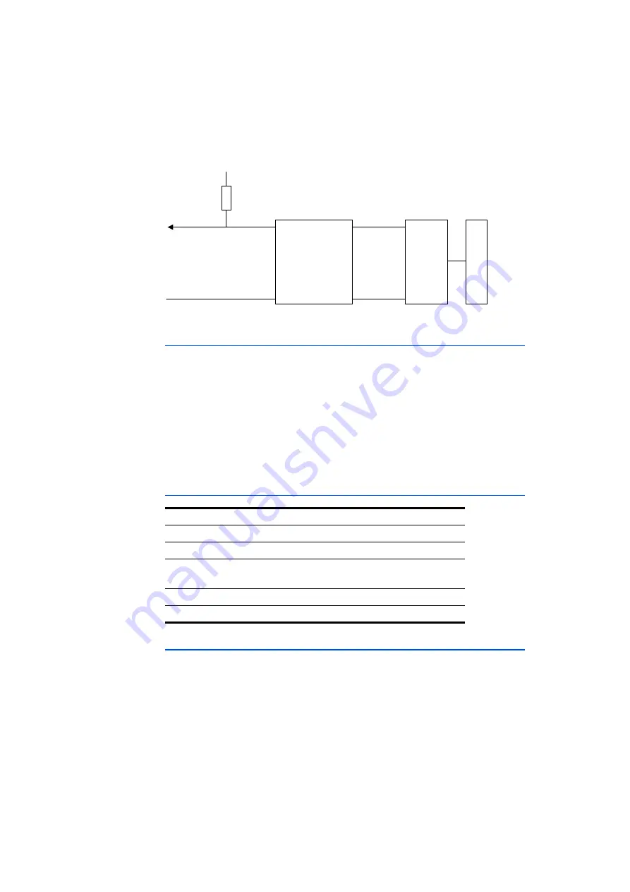
Fig. 3-6 shows the block diagram for the digital outputs at X2 SwCtrl and X4
Power I/O.
Fig. 3-6
Digital outputs at X2 SwCtrl and X4 Power I/O
Digital Outputs DIG_OUT_X at X4 Power I/O
The digital outputs DIG_OUT_0...DIG_OUT_3 at X4 Power I/O have the following
properties:
• 4 TTL outputs, galvanically isolated, with a common reference potential
GND_DIG_OUT
• Possibility for switching external relays
• Configurable via RTIO
• Display of error signals in case of overload (see RTC User's Guide)
The pin assignment of X4 Power I/O is located in Tab. 4-4 on page 46.
Technical Data of TTL Signals at X2 SwCtrl and X4 Power I/O Outputs
3.5
Main Relay Control MRC (X4 Power I/O)
The MRC (Main Relay Control) signal has the following properties:
• Controllable current source/drain
• Use as main relay simulation is possible, +VBAT drawn from Battery Input
X3 (before the switches)
• Switching b/-VBAT possible via software
• Minimum voltage of 6 V must be present to generate a usable MRC signal
• Setting range of current source/drain possible from 0 mA to 150 mA in
increments of 1 mA
Output
Data
Output voltage
Open drain TTL
Output current
max. 11 mA
Overvoltage protection
X2: up to ±20 V
X4: up to ±60 V
Galvanic isolation
yes
Switching frequency
max. 5 kHz
Digital Output
(X2: DIG_OUT_X,
X4: DIG_OUT_X)
Digital Ground
(X2: GND_DIG_OUT_X,
X4: GND_DIG_OUT)
Overvoltage
Protection
X2: 0 ... 20 V
X4: 0 … 60 V
FPGA
+5 V
galv. isolated
Pull-Up
Resistor
DigOut
GND
ES
5300
B
ac
kp
la
n
e


