8
of 34
V 1.0
www.esavep.com
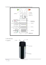
PLEASE NOTE THAT THERE ARE ESSENTIALLY 2 UNITS COMBINED INTO ONE IN THE ESP ECOCENT
AND YOU MUST BE SURE TO UNDERSTAND BOTH ELEMENTS – THE INDIRECT HOT WATER
CYLINDER AND THE AIR SOURCE HEAT PUMP. PLEASE ALSO NOTE THAT THE ECOCENT CAN BE
INSTALLED IN EITHER A VENTED OR UNVENTED SYSTEM.
3.0 COMPONENT CHECK LIST
Before commencing installation of the unit, check that all the components for your unit are
contained in the package. The following components are supplied as standard with all
Ecocents to be installed in a “mains pressure” configuration:
Factory fitted immersion heater (s) and thermal controls.
Cold Water Combination Valve (comprises Pressure Reducing Valve, Stainer and
Check Valve).
Expansion Core Unit (comprises Check Valve and Expansion Valve).
Temperature/Pressure Relief Valve (set at 90 - 95°C/1 Mpa (7bar).
Tundish (included in Cold Water Combination Valve pack).
Factory fitted Indirect Thermostat and Thermal Cut-out.
4.0 SITING THE UNIT
The unit must be vertically floor mounted. It can be placed anywhere convenient provided that the
discharge pipe(s) from Safety valves and air handling duct work can be correctly installed. Areas
that are subject to freezing must be avoided. Ensure that the floor is of sufficient strength to
support the the weight of the unit when it is full of water. Pipe run lengths should be kept as short as possible
for maximum economy and efficiency : the use of secondary returns should be avoided.
Access to controls, immersion heaters and indirect controls must be maintained for servicing
and maintenance of the unit. Please do not install valves or pipe work (except discharge pipe) within 50mm
(2”) of the T&P relief valve to allow insulation to be fitted.
Consideration must be given to the use of insulated ducting to carry air to and from the unit.
Insulated ducting
must
used where condensate may form on the duct work.
IMPORTANT NOTE: DO NOT SITE THE UNIT IN THE SAME ROOM AS AN OPEN FLUED
APPLIANCE OR IN A ROOM FROM WHICH AN OPEN FLUED APPLIANCE TAKES
ITS COMBUSTION AIR, UNLESS THE MATTER HAS BEEN CAREFULLY
CONSIDERED AND ADEQUATE DUCTING AND VENTILLATION HAS BEEN PROVIDED FOR THE
ECOCENT AND THAT THE OPEN FLUED APPLIANCE AIR SUPPLY NEEDS HAVE BEEN
CALCULATED BY AN APPROPRIATELY QUALIFIED SPECIALIST .
Please be sure to use appropriate lifting equipment when moving the unit.
Some things to be considered in positioning the unit:
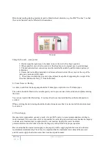
Waste heat is useful heat (picture 1)
The Ecocent can receive ducted waste heat from another area in the building – duct work can be fixed
to the top of the unit and may be up to 8m long. Areas over 8m away can can be used if an additional
in-line fan is fitted in the ductwork. The Ecocent can also draw heat from the room in which it is sited.
Always be sure to site the unit and arrange the duct work to allow for adequate heat availability. This


