6
ASSEMBLY
VICTORY-LX 3 LEG ELECTRIC TABLE BASE
STEP 12
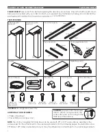
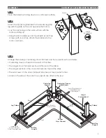
Attach the cross channels to the table.
• Position one U-bracket over each section of cross
channel, between the set screws, as shown (four
brackets total).
• Use the remaining M6x20 Phillips round head
screws (16 total) to fasten the U-brackets to the
work surface.
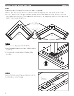
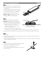
STEP 14
Attach the control unit using the two M5-15 Phillips
round head screws.
• Position the control unit near the back of the
table, on the same side as the digital keypad.
• Be sure that the cable from the keypad can reach
the control unit, and the motor cables can
extend from the control unit to all three motors.
M6x20
M5x15
Control
Unit
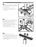
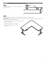
STEP 13
Attach the digital keypad using the three M3-20
Phillips round head screws.
• Position the digital keypad on the left or right side
of the table, according to user preference.
•
the table and expand to make flush. This will
prevent overhang and collision with the keypad.
Mount the keypad 1
/
”
from the front edge of
1 16
Digital
Keypad
M3x20
1
/
”
1 16
MOUNT
FROM EDGE

