background image

7

VICTORY-LX 3 LEG ELECTRIC TABLE BASE 

ASSEMBLY

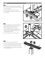
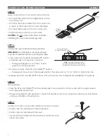
STEP 15

Make connections to the control unit and motors.
• Connect the cable from the digital keypad into

the control unit.

• Connect the motor cables from the control unit 


to each of the three motors on the table legs.

• Connect the power cord to the control unit.
• Plug the power cord into an AC outlet.

CAUTION:

 Do not operate the table until after 


initializing the system. See following step.

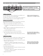
STEP 16

Initialize the system before testing operation.

IMPORTANT:

 The initialization procedure below  

must be completed before operating the table.
• Press and hold  the UP   and DOWN  buttons  

simultaneously for more than 3 seconds. 
—  The legs will begin to move down at half  

speed of normal operation.

• Continue to press  the UP   and DOWN  buttons. 

—  The legs will move down to the lowest position, then rebound 

1

/

16

" to 

3

/

16

" (2mm to 5mm) and stop.

• Release the UP   and DOWN  buttons at the same time. This completes the initialization procedure.

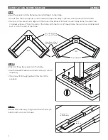
STEP 14

Test operation.
• Press the UP   and DOWN  buttons individually to test operation. End your test with the legs lowered 

and unplug the power cord.

• If there are problems with operation, check that all cable and cord connections are secure. If problems 

continue, call ESI Customer Service.

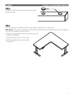
STEP 17

Use the cord clips to secure the cables and cords in position.
• Cables must not interfere with table operation.
• Cables must not interfere with the user.
• 


clips to the table. 

Note:

 Until the table is turned 

upright, the DOWN button points 

up and the UP button points down.

Press and Hold

UP and DOWN Buttons

Cord Clip

M3.5x16

Digital

Keypad

Cable

Power

Cord

Motor

Cables

Summary of Contents for 3V-LX-C3636-24 Series

Page 1: ...VICTORY LX Model 3V LX C4848 24 ___ Model 3V LX C4848 30 ___ Model 3V LX C4836 24 ___ Model 3V LX C4836 30 ___ Model 3V LX C3636 24 ___ Model 3V LX C3636 30 ___ ___ SLV BLK or WHT 3 LEG ELECTRIC TABLE...

Page 2: ...trations show 90 tables 120 tables are illustrated only to show the difference in attachment to the center leg brackets CAUTION Always check that screws used to attach components to the work surface a...

Page 3: ...d top supports as shown below Positioning does not need to be exact at this time The longer cross channels are toward the rear of the table The longer sections of the cross channels are toward the sid...

Page 4: ...loosen all 16 set screws on the inward side of the cross channels Position the outer leg columns and top supports so that the outer top supports are approximately 1 25mm from the ends of the table an...

Page 5: ...nd brackets see illustration Use a 5mm Allen key to secure the screws STEP 8 Attach the feet to the outer leg columns Place the square opening on the foot over the leg The shorter side of the foot sho...

Page 6: ...e the rear cross channels will be 6 from the rear of the table With feet for a 30 deep table the rear cross channels will be 9 from the rear of the table STEP 10 Attach all three top supports to the t...

Page 7: ...ntrol unit near the back of the table on the same side as the digital keypad Be sure that the cable from the keypad can reach the control unit and the motor cables can extend from the control unit to...

Page 8: ...of normal operation Continue to press the UP and DOWN buttons The legs will move down to the lowest position then rebound 1 16 to 3 16 2mm to 5mm and stop Release the UP and DOWN buttons at the same t...

Page 9: ...ides 26 total STEP 19 IMPORTANT There must be 1 25mm of clearance on all sides of the work surface and other moving parts to ensure free unobstructed movement Adjust the leveling glides on the feet to...

Page 10: ...t the minimum height of the table Raise or lower the table to the desired minimum height Press and hold S then press and hold 1 Continue to press both buttons for about 3 seconds The letter L appears...

Page 11: ...3 16 2mm to 5mm and stop Release the UP and DOWN buttons at the same time This completes the initialization procedure If one or more motors are changed in a system the control unit must be reset to f...

Page 12: ...800 833 3746 esiergo com 2017 ESI Ergonomic Solutions All rights reserved 3V LX Rev A 7 17...

Reviews: