2
ASSEMBLY
VICTORY-LX 3 LEG ELECTRIC TABLE BASE
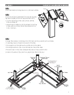
STEP 1
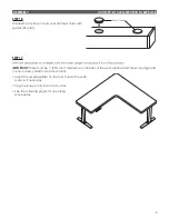
Place the table top facing down on a soft clean surface.
STEP 2
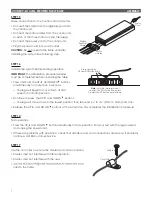
Attach the center leg brackets to the center leg (the
leg with the glide on the end opposite the motor).
• Lay the center leg on the work surface with the
motor pointing up.
• Using the 5mm Allen key and four M6x18 socket cap
screws (with round tip), attach the brackets to the
motor, as shown.
STEP 3
Arrange the side legs, center leg, cross channels and top supports as shown below.
• Positioning does not need to be exact at this time.
• The longer cross channels are toward the rear of the table.
• The longer sections of the cross channels are toward the sides.
• The set screws on the cross channels face inward, toward each other.
• Holes on the sides of the outer top supports are offset to the rear.
Center Leg Column
with Brackets
Leg Column
Leg Column
Left Top
Support
Center Top
Support
Right Top
Support
Shorter
Cross Channel
Set Screws
Face Inward
Front
Rear
Large Holes
Face Outward,
Offset Toward Rear
Small Top Holes for
Center Bracket
Attachment
M6x18
Round Point
Motor
Inner
Cross
Channels
Longer
Cross Channel

