13
3.0 INSTALLATION
3.1 LOCATION
Several factors should be considered when locating the
unit for use. Adequate ventilation is necessary to provide
cooling, and the amount of dirt and dust to which the
machine is exposed should be minimized. There should
be at least 18 inches of unrestricted space between the
machine’s side and rear panels and the nearest obstruc-
tion to provide freedom of air movement through the power
source.
Installing or placing any type of filtering device will restrict
the volume of intake air, thus subjecting the internal com-
ponents to overheating. Warranty is void if any type of
filtering device is used.
3.2 ELECTRICAL INPUT CONNECTIONS
A cord with plug attached is provided. Connect the plug to
a properly grounded and protected (fuse or circuit breaker)
230 Vac receptacle.
Before making any connections to the power supply
output terminals, make sure that all primary input
power to the machine is deenergized (off) and that
input power cable is unplugged.
3.2.1 INPUT ELECTRICAL REQUIREMENTS
The primary input voltage requirements are shown on the
power source nameplate. The power source is designed
to be operated from 208/230 vac single phase 50/60 Hz.
SECTION 3
INSTALLATION
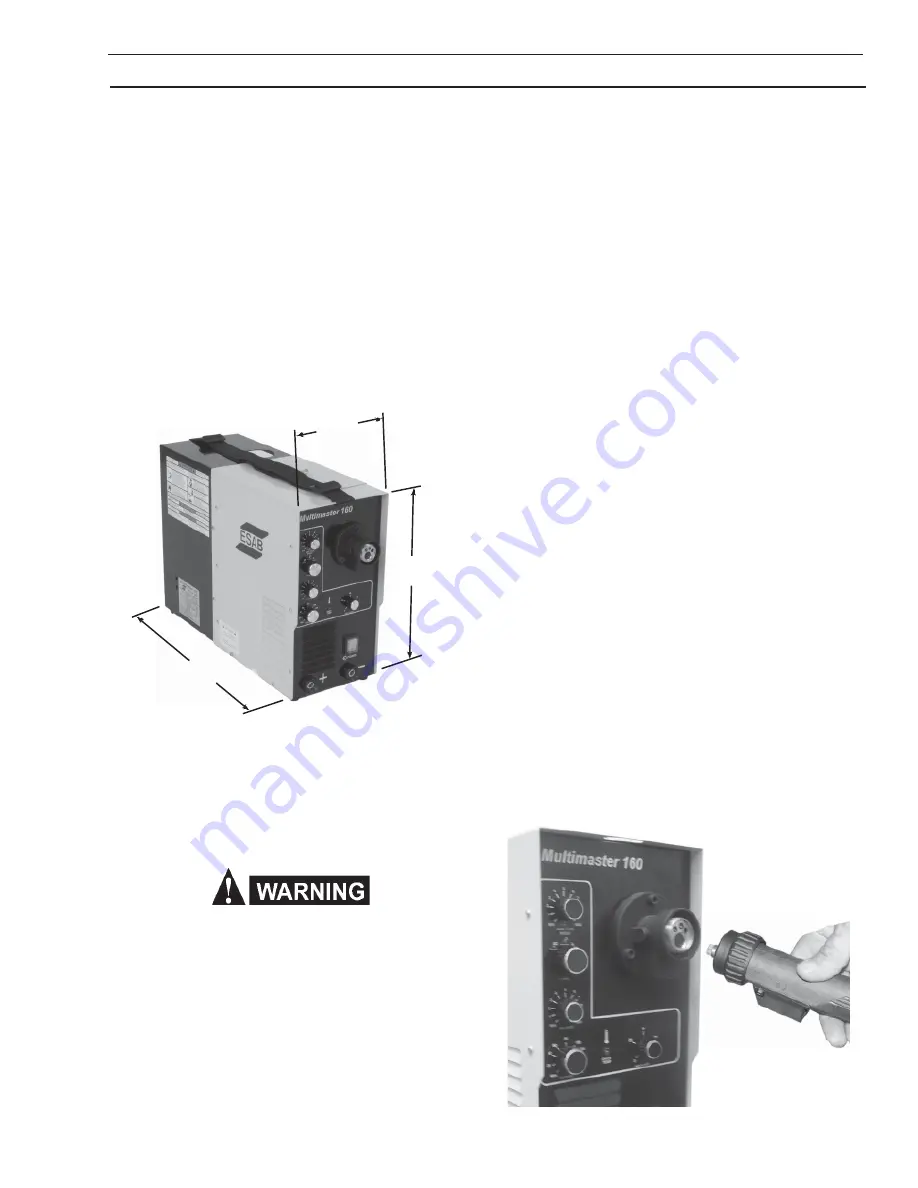
Figure 2 - Dimensions
22.4”
560 mm
9.2”
230 mm
15.4”
385 mm
3.2.2 INPUT PLUG
The input power cord is provided with an attachment plug.
The
plug will mate with a 250 volt, 50 Amp receptacle con-
forming to NEMA 6-50R configuration. The receptacle
must be wired to a separately fused disconnect or circuit
breaker by a qualified electrician.
3.3 SECONDARY OUTPUT CONNECTIONS
The Multimaster 160 Welding System has an internal Po-
larity changeover for the MIG Process located under the
Hinge Cover. Front panel output receptacles make for easy
polarity changeover for TIG and STICK. See Sections
4.2.1, 4.2.2 and 4.2.3 for specific details on Connect Leads
and Cables for your application. Also the MIG torch con-
nections are external allowing easy changes.
3.4 WIRE FEEDER MECHANISM
3.4.1 DRIVE ROLLS (Figure 5 and 7)
When viewing the drive roll, the stamped designation fac
ing
you is the groove in use. The drive roll has two grooves:
the small groove feeds .030 in. diameter wire, the large
groove feeds .035 in. wire. The groove nearest the gear
motor feeds the wire. If the required groove is not cor-
rectly positioned, perform the following:
A. Release the pressure drive roll lever.
B. Remove the screw holding the drive roll.
C. Reverse the drive roll on the drive roll shaft.
D. Replace the screw and tighten.
E. Secure the pressure drive roll assembly.
3.4.2 TORCH INSTALLATION
A Mig torch with a euro-type adapter is supplied as standard
equipment with the Multimaster 160 System. This torch
connects directly to the fitting mounted on the front panel.
Line up matching holes, push on and tighten locking collar.
As shipped from the factory, the euro or common connec-
tor type torches are set-up for D.C.R.P. welding polarity
(See Figure #3).
Figure 3 - Torch Connection
Summary of Contents for MultiMaster 160
Page 1: ...MultiMaster 160 Mig Tig Stick Welding Package F15 678 D 07 2005 Instruction Manual...
Page 4: ...4 Table of Contents...
Page 24: ...24 12 11 10 14 6 5 16 3 7 4 15 8 13 18 17 19 20 Feed Motor SECTION 6 REPLACEMENT PARTS...
Page 26: ...26 Multimaster 160 Bottom Plate 61 62 63 68 64 67 66 65 SECTION 6 REPLACEMENT PARTS...
Page 28: ...28 Notes...
Page 29: ...29 Notes...
Page 30: ...30 Notes...


