26
3.6 connectIon of shIelDIng gas supplY
The R-33-FM-580 Regulator-Flowmeter is designed for use
with an argon or argon-mix cylinder of shielding gas. It is
adjustable for delivering up to 50 cfh through the torch.
Do Not adapt R-33-FM-580 for use with CO
2
. Relief device
may rupture if CO
2
is used with the R-33-FM-580. For CO
2
service, order R-33-FM-320, P/N 21558.
a. With the cylinder cap in place CAREFULLY slide
the cylinder onto the cylinder tray.
b. Using the chain, secure the cylinder to the unit.
c. Unscrew the cylinder cap.
never stand directly in front of or behind the regulator
when opening the cylinder valve. always stand to one
side.
d. Crack the cylinder valve for an instant to blow
away dirt or dust which may have accumulated in
the valve outlet. Be sure to keep your face away
from the valve outlet to protect your eyes.
e. Attach the regulator to the cylinder valve, tighten the
union nut securely with a 1-1/8in. wrench.
f. Attach the gas hose from the rear of the Migmaster
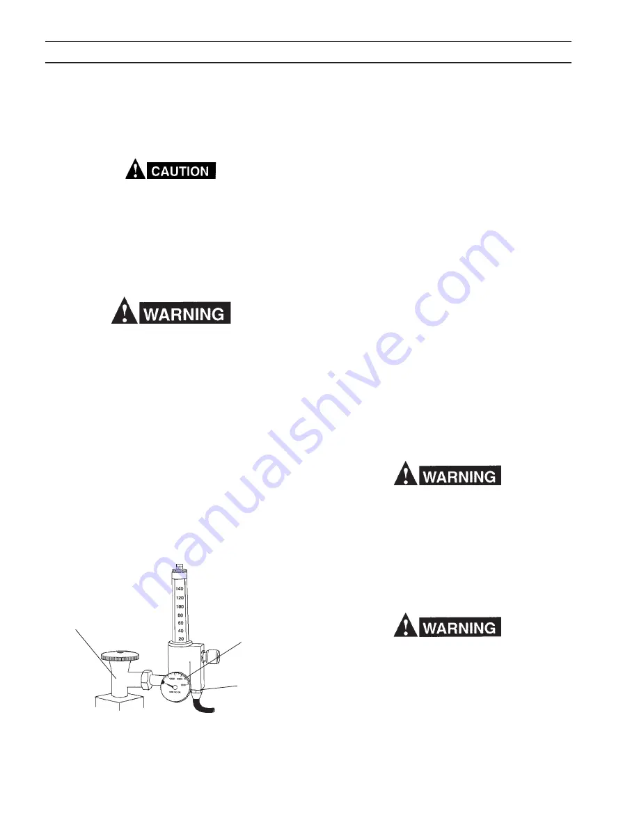
275 to the regulator outlet connection (see Fig. 3.9).
g. Slowly open the cylinder valve a fraction of a turn.
When the regulator pressure gauge pointer stops
moving, open the cylinder valve fully.
OUTLET
CONNECTION
CYLINDER
PRESSURE
GAUGE
CYLINDER
VALVE
sectIon 3
InstallatIon
h. Using a leak test solution, such as P/N 998771 (8 oz.
container) or soapy water, test for leakage about the
cylinder valve stem, the regulator inlet connection,
and the hose connections at the regulator and at the
Migmaster 275 for leakage. Correct any leaks before
starting work.
i. If work is to be stopped for a half-hour or more, or
the regulator is to be removed from the cylinder, shut
down the regulator as follows:
a. Close the cylinder valve.
b. Release gas from the regulator by closing the torch
trigger lever.
c. When pressure gauge drops to zero, the regulator
is de-pressurized and shutdown.
j. Each regulator is equipped with a porous metal
inlet filter, P/N 71Z33, pressed into the regulator
inlet nipple. No. regulator should be connected to a
cylinder or station valve unless it contains this filter.
You can replace the filter if you have reason to do so.
To remove a filter refer to the regulator instruction
literature for details.
k. Regulators in need of repair should be returned to your
Welding Equipment distributor or to an authorized
Remanufacturing Center.
If welding is performed in a confined area, shielding
gas leaks could result in a buildup of shielding gas
concentration, displacing oxygen, thereby endangering
personnel enter the area.
3.7 WelDIng caBle connectIons
Connect the work clamp solidly to the workpiece or work
table. Clamp onto a bare metal area.
a good electrical connection to the work is essential
to proper welding operation and to prevent electric
shock.
Welding cables should be kept as short as possible and
be of adequate current carrying capacity. resistance of
the welding cables and connections causes a voltage
drop which is added to the voltage drop of the arc. ex-
cessive cable resistance may result in a reduction of the
maximum usable current output of the equipment.
fig. 3.9 r-33-fM-580 regulator (Illustrated)
Summary of Contents for Migmaster 275
Page 4: ...4 TABLE OF CONTENT ...
Page 20: ...20 section 2 INTRODUCTION ...
Page 28: ...28 section 3 INSTALLATION ...
Page 42: ...42 section 5 SERVICE ...
Page 46: ...46 section 6 REPLACEMENT PARTS ...
Page 48: ......
Page 49: ......
Page 50: ......
Page 51: ......
Page 52: ......
Page 53: ......
Page 54: ......
Page 55: ......
Page 56: ......
Page 57: ......


