25
3.4 torch connectIons
The GunMaster 250 supplied standard with the Migmaster
275 System, is provided with a NAS-type connector which
connects directly to the gun receptacle on the front panel.
Line up the NAS pin to the hole, firmly push on and tighten
the locking thumb screw. Connect the trigger lead to the gun
receptacle and to the trigger receptacle on the machine.
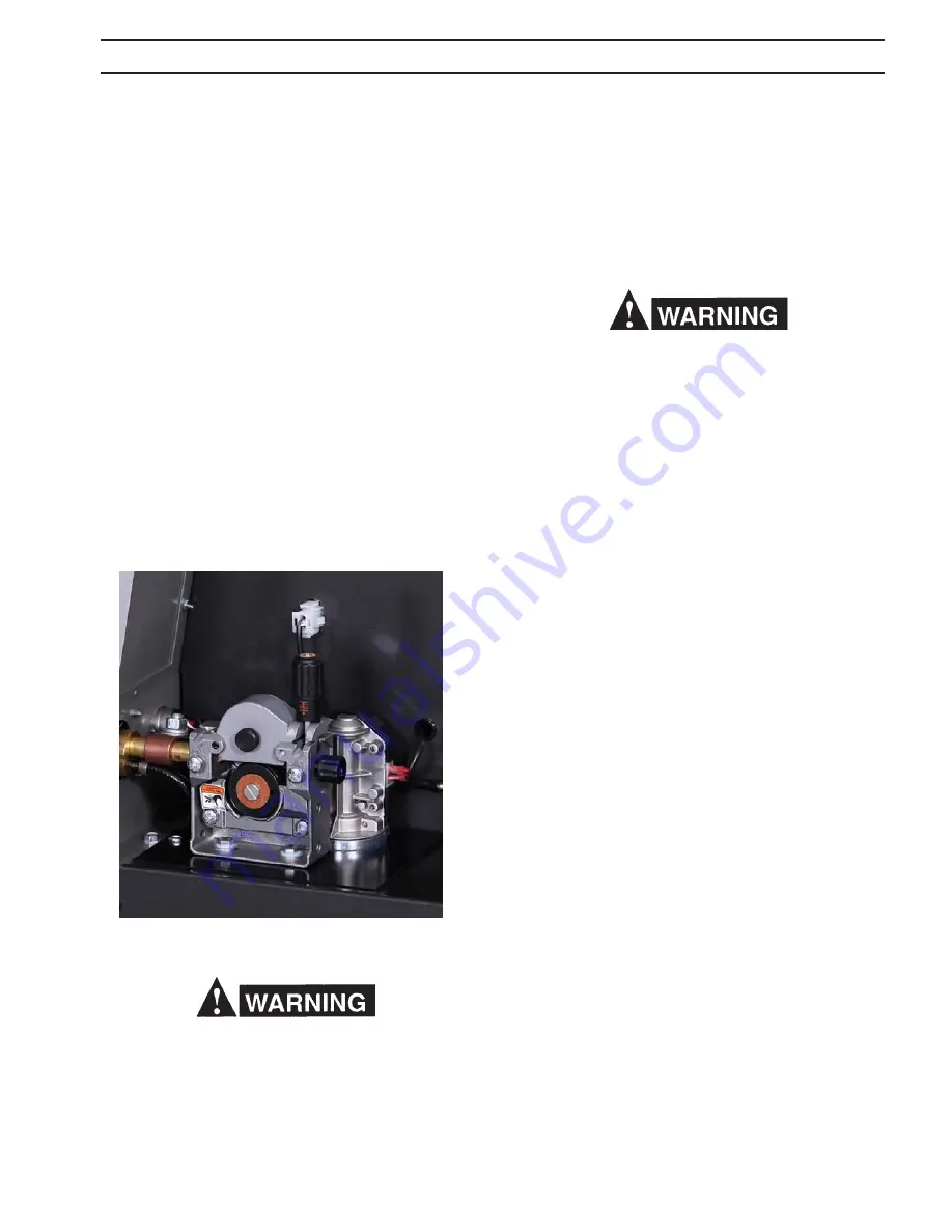
3.5 WIre feeDer MechanIsM
3.5.1 DrIVe rolls
The drive roll has two grooves: the small groove feeds 0.035
in. diameter wire, the large groove feeds 0.045 in. wire. The
groove nearest the gear motor feeds the wire. If the required
groove is not in that position:
A. Release the pressure drive roll lever and lift the
assembly upward.
B. Remove the screw holding the drive roll to
the motor shaft.
C. Reverse the drive roll on the drive roll shaft.
D. Replace the screw and tighten.
E. Secure the pressure drive roll assembly.
3.5.2 WelDIng WIre spool
as with any work area, make sure safety glasses with
side shields are worn when handling or changing wire or
clipping wire off at the spool or at the end of the torch.
hold onto the wire coming off the spool with one hand
before clipping. serious eye injury can result due to the
springiness of the wire which can quickly unravel, or a
cut wire end which may shoot across the room.
Install a spool of welding wire on the hub as follows:
A. Unscrew spool nut from hub.
B. Place wire spool on hub to rotate clockwise as wire
is unwound; hub pin must engage hole in spool.
C. Replace nut.
3.5.3 threaDIng WelDIng WIre
When the power switch is on, and gun trigger is de-
pressed, the electrode becomes electrically hot, and
the feed rolls are activated. Keep fingers clear of the
drive mechanism.
A. Turn power switch to "OFF".
B. Release pressure drive roll assembly. Check that
proper wire diameter groove is in the inner posi
tion.
CAUTION: Before threading welding wire through casing,
make sure chisel point and burrs have been
removed from wire end to prevent wire from
jamming in gun casing or liner.
C. Feed the wire from the spool through the inlet
guide, across the drive roll groove and into the
outlet guide.
Make sure that the proper “outlet guide” is inserted into the
front-panel gun adapter for the size and type of wire being
used, see Table 2.2 for wire feed accessories (Section 2.5).
To insure proper wire feeding, it is important that the wire
be kept clean and that the drive rolls be periodically cleaned
of any chips or scale that might be carried into the gun liner
and cause sticking.
D. Lower pressure roll assembly and secure. Check
that the gears mesh. Turn the power switch to
"ON". Feed wire through to gun tip with gun trigger.
3.5.4 BraKe Drag aDJustMent
Brake disc friction should provide enough drag to keep the
wire spool or core from spinning freely after wire feed stops.
If adjustment is required, turn adjusting screw clockwise to
increase drag, counterclockwise to decrease it. Drag should
be just low enough to limit wire overrun.
sectIon 3
InstallatIon
fig. 3.8 WIre DrIVe asseMBlY
Summary of Contents for Migmaster 275
Page 4: ...4 TABLE OF CONTENT ...
Page 20: ...20 section 2 INTRODUCTION ...
Page 28: ...28 section 3 INSTALLATION ...
Page 42: ...42 section 5 SERVICE ...
Page 46: ...46 section 6 REPLACEMENT PARTS ...
Page 48: ......
Page 49: ......
Page 50: ......
Page 51: ......
Page 52: ......
Page 53: ......
Page 54: ......
Page 55: ......
Page 56: ......
Page 57: ......


