


62
TROUBLESHOOTING
62
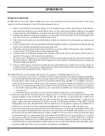
interface adaptor Box
The Interface Adaptor Box is required when using a EPP-202/362 in place of a EPP-201/360.
Connect to Analog Interface on the
EPP-202/362
Connect to J1 (RAS) on the EPP-202/362
The box has 2 LED indicators. The indicator on the left represents the “10s” digits, the indicator on the right rep-
resents the “1s” digits. Count each flash of the indicators to determine the help code number. The indicators will
flash in sequence, pause, and repeat. Example: if the left indicator flashes 2 times, pauses and repeats, and the
right indicator flashes 4 times, pauses and repeats, your help code would be 24. See help code lists for explana-
tion.
LED indicators
Interface Adaptor Box top view
installation:
Remove existing connections from the EPP-201/360 and connect to the Interface Adaptor Box. Use
the existing cables supplied and currently used on your EPP-201/360. The E-stop connector has either a 2-pin or
4-pin connector, determine which connector your equipment has and connect to the appropriate connector.
The paralleled power source connections are not supported with the EPP-202/362 applications.
E-stop connection (2-pin or 4-pin)
Connection from Remote Control on
the EPP-201/360 connects here
Connections made on the front
of the EPP-202/362
Additionally, the internal coolant circulator must be used with the EPP-
202/362, thus any external coolant circulator should be disconnected.
Summary of Contents for 0558011310
Page 2: ...EPP 202 Plasma Power Source 2...
Page 4: ...EPP 202 Plasma Power Source 4...
Page 7: ...SAFETY...
Page 8: ...SAFETY 8...
Page 21: ...DESCRIPTION...
Page 22: ...description 22...
Page 25: ...INSTALLATION...
Page 26: ...installation 26...
Page 39: ...installation 39 J1 RAS Interface Cable CAN Cables...
Page 40: ...installation 40...
Page 41: ...OPERATION...
Page 42: ...OPERATION 42...
Page 50: ...OPERATION 50...
Page 51: ...MAINTENANCE...
Page 52: ...Maintenance 52...
Page 57: ...TROUBLESHOOTING...
Page 58: ...58 TROUBLESHOOTING 58...
Page 65: ...REPLACEMENT PARTS...
Page 66: ...Replacement Parts 66...
Page 68: ...Replacement Parts 68...
Page 69: ...revision history 1 Originally released 01 2015 2 Revision 10 2015 added RotorFlow Sensor...


