installation
37
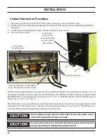
output connection procedure
Front Access
Panel Opened
1. Open access panel on the lower front of the power source by removing four M6 screws.
2. Thread output cables through the openings at the bottom of the power source immediately behind the
front panel.
3. Connect cables to designated terminals mounted inside the power source using UL listed pressure wire
connectors.
4. Close front access panel.
Front Access
Panel Closed
Remove four M6
screws to open
Access Panel
The plasma unit does not have an ON/OFF switch. The main power is controlled through the line (wall) discon-
nect switch.
To ease connections,
thread cables/hoses
through these
3 access holes
Summary of Contents for 0558011310
Page 2: ...EPP 202 Plasma Power Source 2...
Page 4: ...EPP 202 Plasma Power Source 4...
Page 7: ...SAFETY...
Page 8: ...SAFETY 8...
Page 21: ...DESCRIPTION...
Page 22: ...description 22...
Page 25: ...INSTALLATION...
Page 26: ...installation 26...
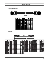
Page 39: ...installation 39 J1 RAS Interface Cable CAN Cables...
Page 40: ...installation 40...
Page 41: ...OPERATION...
Page 42: ...OPERATION 42...
Page 50: ...OPERATION 50...
Page 51: ...MAINTENANCE...
Page 52: ...Maintenance 52...
Page 57: ...TROUBLESHOOTING...
Page 58: ...58 TROUBLESHOOTING 58...
Page 65: ...REPLACEMENT PARTS...
Page 66: ...Replacement Parts 66...
Page 68: ...Replacement Parts 68...
Page 69: ...revision history 1 Originally released 01 2015 2 Revision 10 2015 added RotorFlow Sensor...


