


OPERATION
46
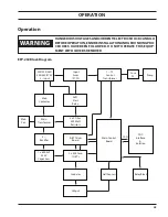
modes of operation
Plasma unit can be operated in Cutting Mode or Marking Mode. The command to operate the machine in Cut-
ting or Marking mode can be received from the CNC or Process controller through CAN (digital) communication
or through analog communication. The default mode of operation is cutting.
Digital communication:
In this mode, the plasma unit and CNC or process controller are communicated through CAN protocol (CAN
connector). Plasma unit recieves the digital and analog inputs required for the process state machine and
transmits the respective digital and output signal to CNC or process controller through digital CAN protocol.
CNC or process controller sends the command to operate the plasma unit either in cutting mode or marking
mode.
A shielded CAN cable, as listed in section 3.8.2, is used to connect CAN connector and customer CNC/pro-
cess controller. There is 120 ohm termination resistor available on control board (PCB1) which is selected by
a switch setting. By default this switch is set to 120 ohm termination resistor position.
note:
Always connect CAN power supply unit at the end of the CAN hub.
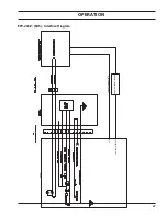
analog communication:
In this mode, the plasma unit and CNC/process controller are communicated through Analog Interface Con-
nector. CNC or process controller closes and opens the relay, which are hard-wired into digital inputs of
microcontroller on PCB1 inside plasma unit, to operate the plasma unit in marking or cutting mode respec-
tively. A shielded DB25-DB25 cable, as mentioned in section 3.8.3, connects the analog interface connector
to the junction box.
Summary of Contents for 0558011310
Page 2: ...EPP 202 Plasma Power Source 2...
Page 4: ...EPP 202 Plasma Power Source 4...
Page 7: ...SAFETY...
Page 8: ...SAFETY 8...
Page 21: ...DESCRIPTION...
Page 22: ...description 22...
Page 25: ...INSTALLATION...
Page 26: ...installation 26...
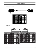
Page 39: ...installation 39 J1 RAS Interface Cable CAN Cables...
Page 40: ...installation 40...
Page 41: ...OPERATION...
Page 42: ...OPERATION 42...
Page 50: ...OPERATION 50...
Page 51: ...MAINTENANCE...
Page 52: ...Maintenance 52...
Page 57: ...TROUBLESHOOTING...
Page 58: ...58 TROUBLESHOOTING 58...
Page 65: ...REPLACEMENT PARTS...
Page 66: ...Replacement Parts 66...
Page 68: ...Replacement Parts 68...
Page 69: ...revision history 1 Originally released 01 2015 2 Revision 10 2015 added RotorFlow Sensor...


