


3
10
LAN 10/100/1000M
(RJ-45)
The
NVR
is capable of networking and it allows the videos to be
viewed over the LAN network or the Internet by using the Internet
Explorer.
11 e-SATA Port
Users can connect an e-SATA storage device via this port.
12 USB 2.0 Port
The USB 2.0 port locates on the rear panel is for users to connect
external USB devices to the unit, such as ThumbDrive
®
or a USB
mouse.
NOTE:
Currently, the
“plug and play” function is only supported for specific models. Please
contact the supplier for more information. Furthermore, the IP address of the IP cameras has
to be set to default or static before connecting to the NVR. Otherwise the NVR will not be
able to recognize the existence of the IP cameras.
When Main Monitor Cannot Correctly Display:
The preset monitor resolution is
720P
. If the main monitor connected cannot support 720P, please
connect a BNC monitor and follow steps below to change the resolution setting.
Press and hold
CALL
to enter 2nd Main Monitor (BNC) control mode.
Press
MENU
to enter the OSD main menu. Select the administrator account
“
admin
” and enter
the preset password
“
1234
”
to login.
Go to <
Monitor Setup
>
<
VGA Resolution
> and select a suitable resolution setting.
Press and hold
CALL
again to return to the 1st main monitor control mode.
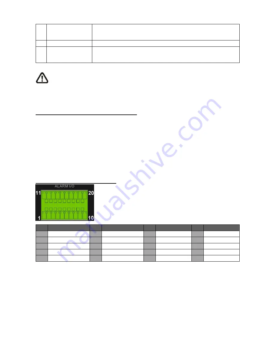
Pin Definition of Alarm I/O & RS-485:
Pin Definition
Pin Definition
Pin Definition
Pin Definition
1
RS485 D+
6
Normal Open A
11
Alarm In 1
16
Alarm In 6
2
RS48
5 D−
7
Ground
12
Alarm In 2
17
Alarm In 7
3
Ground
8
Normal Close B
13
Alarm In 3
18
Alarm In 8
4
Normal Close A
9
Common Node B
14
Alarm In 4
19
N/A
5
Common Node A
10
Normal Open B
15
Alarm In 5
20
N/A


