background image

11  Power Switch 

1.  Press this switch to power on the NVR. The LED will be lighten up. 
2.  Press and hold this key to quick shutdown the NVR. The LED will blink 

when the power source is still available. 

12  USB 2.0 Ports 

The USB 2.0 ports allow users to connect an external USB device to the 
unit, such as a USB ThumbDrive

®

 or a USB mouse. 

13  COPY 

This key is also used for marking time in quick video export


function. 

14  FREEZE 

Press this key to freeze the current viewing screen. 

15  PLAY 

Press once to start the playback of recorded video. Press again to exit. 

16  SEARCH 

Press this key to search recorded video by date/time or event. 

17  ZOOM/ENTER 

1.  In  OSD  menu  or  selection  interface,  press  these  key  to  make  the 

selection or save settings.   

2.  In  live  full-screen  viewing  mode,  press  this  key  to  view  a  2×  zoom 

image; press it again to return. 

18  ESC 

Press this key to cancel or exit from certain control mode. 
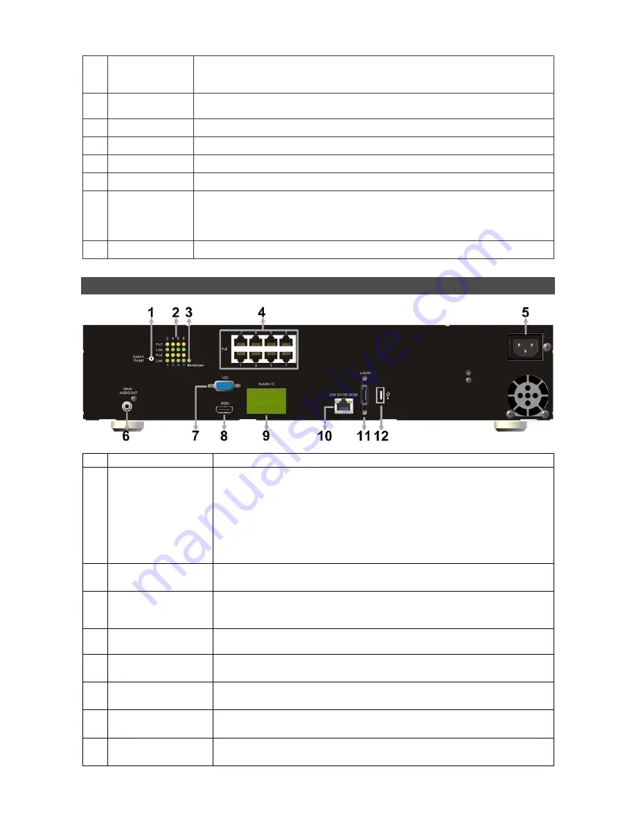
 

Rear Panel 


Switch Reset 

This is for reset of the PoE switch when needed to. 

LED Indication 

Each IP camera has two corresponding LEDs: 
1.  The lightened orange LED represents the IP camera is connected 

and  power  is  supplied  via  PoE.  When  the  LED  is  off,  either  the 
power is separately connected or the IP camera is not connected. 

2.  The blinking green LEDs represents data transmission goes from 

the IP cameras to the NVS. When the LED is not on, that means 
the IP camera is not connected. 

Backplane 

This LED will blink to indicate there is data transmission between the 
PoE board and the Main board. 

PoE Ports 

The  optional  PoE  ports  offer  direct  connections  to  four  IP  cameras. 
The IP cameras can be 

“plug and play” if the function is enabled in the 

OSD menu. 

Power Jack 

Connect the  power  supply  cord  shipped  with  the  NVR.  Use  of  other 
power supply cords may cause overloading. 

Main Monitor 
Audio Out 

A RCA connector is provided to output audio associated with the main 
monitor. 

Main Monitor 
(Digital Output) 

A  digital  output  connector  is  provided  for  connection  to  a  displaying 
device that transfers data digitally to show the best video quality. 

Main Monitor 
(VGA) 

A  VGA  output  connector  is  offered  for  connecting  to  a  VGA  main 
monitor.   

Alarm I/O & 
RS-485 

The  NVR  provides  alarm  I/O  and  RS-485  ports  that  offer  users  the 
flexibility required to connect the unit to other devices. Refer   

Summary of Contents for EDNS P6000

Page 1: ...Live and Playback modes press any key to view the corresponding video in full screen 2 In input interface 1 10 can be used for direct input of numbers 0 9 3 In Dome Camera Control mode 1 is for enter...

Page 2: ...ightened orange LED represents the IP camera is connected and power is supplied via PoE When the LED is off either the power is separately connected or the IP camera is not connected 2 The blinking gr...

Page 3: ...When Main Monitor Cannot Correctly Display The preset monitor resolution is 720P If the main monitor connected cannot support 720P please connect a BNC monitor and follow steps below to change the res...

Page 4: ...setup some basic configuration of the NVR The basic configuration can be set via either the NVR or NVRRemote the remote software Enter OSD Main Menu Press MENU to enter the OSD main menu Select the ad...

Page 5: ...ys to move the cursor to the item Use LEFT RIGHT keys to access each section of the value and press ENTER then change the value using UP DOWN keys PPPoE users must set the PPPoE Account PPPoE Password...

Page 6: ...fied From time Move the cursor to End and press ENTER will start playing recorded video from the specified End time Move the cursor to Select and press LEFT RIGHT to choose date time Press ENTER and a...

Page 7: ...s ENTER to select or de select a channel Move the cursor to Event List and press ENTER to list the event video of the selected channels The list displays each event by date time triggered camera and a...

Page 8: ...all Monitor 15 Stamp A 3 Monitor Active Inactive 16 Stamp B 4 Sequence 17 Lock 5 Record 18 Disk Error 6 Event Record 19 Disk Full 7 Freeze Live Mode 20 Disk Overheat 8 Dome Camera Control 21 No Disk 9...

Page 9: ...Level Under ActiveX controls and plug ins set all items to Enable or Prompt Click OK to accept the settings and close the Security Settings screen Using the Remote Software Start the IE and enter the...

Page 10: ...up Menu 2 Deflicker On Off at Playback 11 Search Event List 3 Smoothen the Image 12 Capture Snapshot 4 Audio On Off 13 4 3 Viewing Aspect 5 2 way Audio Talk 14 HDD Health Status 6 Select Camera 15 Pla...

Page 11: ...Open and the file selection screen is displayed Select the drv video file to playback and click OK Click OK to start the playback or click Cancel to abort View the video playback using the Playback co...

Reviews: