


Unit Description, TMA-CM
The TMA is always used together with its connection cable and
connection plate for Bias injectors. The connection plate contains
filtering equipment.
An indicator on the front panel is lit for each TMA in operational mode.
Whether an indicator is lit dpeends also on the actual configuration, see
Chapter Radio Configurations, RBS 2106 and RBS 2206.
If the TMA or the feeder cable is short-circuited, the TMA-CM limits
the current to 500 mA.
The power cable to the Bias Injector is supervised and an alarm is
generated if the cable is not connected. The alarm is transmitted on the
IOM bus.
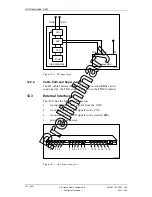
11.3
External Interfaces
P008300A
Fault
Oper.
1
2
3
4
5
6
TMA oper.
TMA power
TMA CM-01
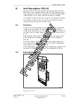
Figure 96
TMA-CM
The TMA-CM has the following external interfaces:
•
Power in (+24 V DC)
•
IOM-bus
•
TMA power connector
168 (485)
EN/LZT 720 0008
P2A
2001-11-28
© Ericsson Radio Systems AB
— All Rights Reserved —
P
re
li
m
in
a
ry
Summary of Contents for RBS 2106
Page 2: ...P r e l i m i n a r y ...