


Unit Description, TMA-CM
11
Unit Description, TMA-CM
The Tower Mounted Amplifier Control Module (TMA-CM), together
with the Bias Injectors, supplies power to the Tower Mounted
Amplifiers (TMA). It can also monitor and control the TMAs.
11.1
Block Diagram
x
x
x
x
x
x
x
x
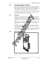
Fault
Oper.
TMA1
TMA2
TMA3
TMA4
TMA5
TMA6
IOM Bus
+24V DC
TMA1
TMA2
TMA3
TMA4
TMA5
TMA6
DC/DC
Converter
Indicator
Control
TMA
Support
Measurement
Indicators
P008456B
Figure 95
Block diagram
11.2
Functions
The TMA-CM has the following functions:
•
DC-voltage supply for up to six TMAs
•
Control of TMA (on/off)
•
DC-current and voltage measurement
•
Supervision indicators
•
Short circuit protection
•
Cable supervision
The TMA-CM supplies up to six TMAs with 15 volt and maximum 500
mA to each TMA. The power output is a 15-pole d-sub connector on
the front of the TMA-CM. A TMA consumes in general 70 - 200 mA.
The TMAs can be individually powered on and off by commands from
the DXU.
The current and voltage to each TMA is measured, and an alarm is
generated if the values are outside specified values, indicating that a
TMA is not working properly. The alarm is transmitted to the DXU on
the IOM bus.
EN/LZT 720 0008
P2A
2001-11-28
167 (485)
© Ericsson Radio Systems AB
— All Rights Reserved —
P
re
li
m
in
a
ry
Summary of Contents for RBS 2106
Page 2: ...P r e l i m i n a r y ...