This manual is published by Ericsson Inc., without any warranty. Improvements and changes to this manual necessitated by typographical errors,
inaccuracies of current information, or improvements to programs and/or equipment, may be made by Ericsson Inc., at any time and without notice. Such
changes will be incorporated into new editions of this manual. No part of this manual may be reproduced or transmitted in any form or by any means, electronic
or mechanical, including photocopying and recording, for any purpose, without the express written permission of Ericsson Inc.
Copyright © June 1996, Ericsson, Inc.
NOTE
Repairs to this equipment should be made only by an authorized service technician or facility designated by the supplier.
Any repairs, alterations or substitution of recommended parts made by the user to this equipment not approved by the
manufacturer could void the user’s authority to operate the equipment in addition to the manufacturer’s warranty.
NOTICE!
This manual covers Ericsson and General Electric products manufactured and sold by Ericsson Inc.
TABLE OF CONTENTS
Page
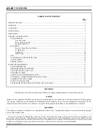
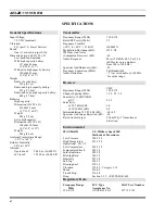
SPECIFICATIONS ..................................................................................................................................................... 4
GENERAL .................................................................................................................................................................. 5
CONTROLS ................................................................................................................................................................ 6
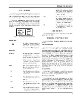
INDICATORS ............................................................................................................................................................. 7
OPERATION............................................................................................................................................................... 7
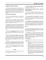
THEORY OF OPERATION ....................................................................................................................................... 7
TRANSMITTER ................................................................................................................................................... 7
Low Pass Filter .......................................................................................................................................... 7
Tx/rx Antenna Switch ................................................................................................................................ 7
Rf Power Control........................................................................................................................................ 9
RECEIVER ............................................................................................................................................................ 9
Receiver Front End And Mixer.................................................................................................................. 9
45 Hhz Filter............................................................................................................................................... 9
Synthesizer................................................................................................................................................ 10
Audio Logic .............................................................................................................................................. 10
CPU ...................................................................................................................................................................... 10
AUDIO SIGNAL PROCESSOR U401............................................................................................................... 10
CLOCK SHIFT .................................................................................................................................................... 10
POWER SUPPLY ................................................................................................................................................ 11
RADIO PROGRAMMING ...................................................................................................................................... 11
PC PROGRAMMING ......................................................................................................................................... 11
PROGRAMMABLE FEATURES ...................................................................................................................... 11
CHANNEL BUSY LOCK-OUT......................................................................................................................... 11
CHANNEL GUARD ........................................................................................................................................... 11
SQUELCH TAIL ELIMINATION (STE)........................................................................................................... 11
AUTOMATIC NUMBER IDENTIFICATION (ANI) ....................................................................................... 11
CARRIER CONTROL TIMER .......................................................................................................................... 13
TYPE 99 TONE DECODE ................................................................................................................................. 13
TELEPHONE INTERCONNECT (DTMF) (KPC-400 ONLY) ....................................................................... 13
The software contained in this device is copyrighted by Ericsson Inc. Unpublished rights are reserved under the copyright
laws of the United States.
NOTICE!
AE/LZB 119 1874 R1A
2
Summary of Contents for KPC-300
Page 1: ...ericssonz Maintenance Manual KPC 300 400 Portable Radio ...
Page 8: ...Figure 5 Block Diagram AE LZB 119 1874 R1A 8 ...
Page 29: ...EXPLODEDVIEW EXPLODED VIEWS AE LZB 119 1874 R1A 29 ...
Page 30: ...COMPONENT LAYOUT TOP BOTTOM SUB BOARD AE LZB 119 1874 R1A 30 ...
Page 31: ...COMPONENT LAYOUT MAIN BOARD TOP AE LZB 119 1874 R1A 31 ...
Page 32: ...COMPONENT LAYOUT MAIN BOARD BOTTOM AE LZB 119 1874 R1A 32 ...


