Ericsson KPC-300 Maintenance Manual Download Page 10

Synthesizer

The synthesizer circuit generates all transmit and receive

RF frequencies. This circuit consists of synthesizer IC U302,
temperature compensated crystal oscillator (TCXO) U303,
voltage controlled oscillator (VCO) U301 and associated
loop filter circuitry.

The VCO operates at the transmitter frequency during

transmit function and 45 MHz above the receive frequency
during the receive function. The synthesizer is controlled by
the CPU. Frequency stability is maintained by the TCXO
module.

A portion of the VCO output is applied to the synthesizer

IC and  divided by 65/64 dual modulus prescaler, which is
set by pulse swallow counter A and programmable counter
B to provide a 5 kHz or 6.25 kHz output for comparison with
a reference signal. The reference signal is derived from the
12.8 MHz TCXO module. The synthesizer IC divides the
12.8 MHz signal down to the 5 or 6.25 kHz signal. (The
KPC-300/400 PC Programming Software will only permit
synthesis of transmit or receive frequencies that are integer
multiples of 5 or 6.25 kHz. Other frequencies cannot be input
into the radio’s personality. The synthesizer’s default phase
lock frequency is 5.0 kHz. If the frequency to be synthesized
is not an integer multiple of 5 kHz, the synthesizer’s phase
lock frequency will be 6.25 kHz.) An unlock detector is used
to prevent transmission when the frequency synthesizer is
unlocked.

Audio modulation from the Audio Signal Processor

(ASP) IC U401 is applied to the VCO modulation input via
amplifier U402 and the TCXO modulation input via ampli-
fier U402. The gain of U402 is adjusted dependent upon the
channel spacing mode of the radio. In the 25 kHz channel
space mode, U418 is open-circuited, removing R453 from
being in parallel with R411. In the 12.5 kHz channel space
mode, U418 is short-circuited, placing R453 in parallel with
R411 and reducing the transmitter audio gain by a factor of
two. (This establishes the 5 kHz maximum frequency devia-
tion for 25 kHz channel spacing and the 2.5 kHz maximum
frequency deviation for 12.5 kHz channel spacing.) VR403
and VR402 are adjustable to provide a constant modulation
flatness for voice audio and Channel Guard (CG) and Digital
Channel Guard (DCG) sub-audible modulation.

MOSFET transistor Q316 is turned on during the transmit

mode to change the loop gain in order to get lower modula-
tion frequency response. A ripple filter, consisting of Q312,
C312 and R331, provides a filtered 4.7 VDC to the VCO to
improve the phase noise characteristic of the receiver local
injection signal for enhanced receiver performance for adja-
cent channel selectivity, intermodulation and FM hum and
noise.

Audio Logic

The audio logic section consists of CPU U404, Audio

Signal Processor (ASP) IC U401, EEPROM U406 and asso-

ciated components. The CPU controls all radio operations.
The EEPROM  contains the personality data and the align-
ment data.

CPU

The CPU contains the LCD controller, LED controls, 32k

bytes of ROM, 1k byte of RAM, an 8-channel A/D converter
and a 2-channel D/A converter. The CPU generates DTMF
tones, alert tones, beep tones, GE-STAR (ANI) codes and
Digital Channel Guard (DCG) encode codewords. The DCG
encode codeword from the CPU is applied to a low pass filter
in the ASP IC U401 and summed with the voice signal at
U402. Received DCG codewords and Type 99 tones from the
ASP U401 are supplied and decoded by the CPU.

AUDIO SIGNAL PROCESSOR U401

The ASP IC U401 contains the CG encoder and decoder,

pre-emphasis audio shaping filters, de-emphasis audio shap-
ing filters, limiter, post-limiter filter (i.e., splatter filter) and
various Switched Capacitor Filters (SCF). U401 generates
CG tones controlled by the CPU. CG and DCG sub-audible
modulation signals are summed with the voice audio signal
at op-amp U402 and supplied to the VCO and TCXO modu-
lation inputs.

The demodulated audio signal from IF IC U101 can

provide voice signal information, CG tones, DCG codewords
and Type 99 two-tone sequential information. CG tones are
filtered by a tone filter and decoded in the ASP. DCG code-
words are filtered by the tone filter and input to multiplexer
U417. Type 99 tones are filtered by a bandpass filter and also
input to U417. Multiplexer U417 selects either the DCG or
Type 99 signals, outputs the signal to a comparator to
“square” the signal to a TTL level digital waveform and then,
sends the digitized signal to the CPU for detection.

Before the transmit voice audio signal is inputted to the

ASP, it can be optionally mixed with DTMF or GE-STAR
(ANI) encode signals. These baseband signals are pre-em-
phasized, bandpass filtered, hard limited, run through a post-
limiter filter (splatter filter) and then summed at op-amp
U402 with  CG tones or DCG codewords.

CLOCK SHIFT

The CPU uses a nominal 7.3728 MHz clock frequency,

which is divided down to 3.6864 MHz to become the clock
frequency input provided to the ASP IC U401. Harmonics of
this clock frequency can potentially interfere with the per-
formance of the transmitter and receiver, producing self-qui-
eting “beat” notes at specific receiver frequencies or
producing an audio whine at specific transmitter frequencies.
A clock shift can be programmed for each channel’s receive
and/or transmit frequency to move the potentially interfering
harmonics of the microprocessor clock frequency. The mi-
croprocessor clock frequency is shifted more than +100 ppm,
effectively moving potentially interfering clock harmonics
off-channel.  

AE/LZB 119 1874 R1A

10

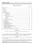
Summary of Contents for KPC-300

Page 1: ...ericssonz Maintenance Manual KPC 300 400 Portable Radio ...

Page 2: ...not approved by the manufacturer could void the user s authority to operate the equipment in addition to the manufacturer s warranty NOTICE This manual covers Ericsson and General Electric products manufactured and sold by Ericsson Inc TABLE OF CONTENTS Page SPECIFICATIONS 4 GENERAL 5 CONTROLS 6 INDICATORS 7 OPERATION 7 THEORY OF OPERATION 7 TRANSMITTER 7 Low Pass Filter 7 Tx rx Antenna Switch 7 R...

Page 3: ...up Call Quick Call Format 18 ALIGNMENT 20 TEST EQUIPMENT 20 Initial Setup 20 BATTERY INFORMATION 21 CHARGE BEFORE USING 21 RECHARGING THE BATTERY 21 INSTALLING THE BATTERY PACK 21 REMOVING THE BATTERY PACK 21 BATTERY CARE MAINTENANCE 21 BATTERY RECYCLING 22 OPERATING TIPS 22 EFFICIENT RADIO OPERATION 22 ANTENNA CARE AND REPLACEMENT 22 ELECTRONIC DEVICES 22 AIRCRAFT 22 BLASTING AREAS 22 POTENTIALLY...

Page 4: ...z 2 5 5 FM Hum And Noise Companion Receiver dB 40 Audio Response Meets TIA EIA 603 Par 5 2 6 6dB octave pre emphasis from 300 to 3000 Hz Spurious And Harmonics dB 65 Frequency Separation MHz Full Bandwidth Audio Distortion 5 at rated audio 1000 Hz for entire range Receiver VHF Frequency Range MHz 150 8 174 Channel Spacing kHz 12 5 25 30 Sensitivity 12 dB SINAD µV 0 35 Selectivity 12 5 kHz dB 60 25...

Page 5: ... three 3 buttons on the front panel The KPC 400 contains three 3 buttons along with a twelve 12 button DTMF pad on the front panel The scan function allows monitoring of any or all channels Any channel may be scanned with or without a priority level One channel can be programmed for Priority 1 P1 and another for Priority 2 P2 with any or all remaining channels programmed as non priority channels S...

Page 6: ...ard after three 3 seconds have passed even if Channel Guard protected This permits channel monitoring be fore transmitting If the button is held for more than three 3 sec onds Channel Guard decode will toggle ON or OFF if it is pro grammed on the selected chan nel The Monitor button is also used to reset the radio after a Type 99 call is received Quickly press and re lease the button to reset the ...

Page 7: ...mit high power OPERATION Detail operating procedures are found in Operator s Man ual AE LZT 123 1898 THEORY OF OPERATION Refer to the Block Diagram during the following expla nations TRANSMITTER The transmitter consists of an exciter Q201 PA module U201 auto power control APC U202 with Q202 and Q203 directional coupler Z201 and associated components The local signal input of approximately 0 dBm to...

Page 8: ...Figure 5 Block Diagram AE LZB 119 1874 R1A 8 ...

Page 9: ...set the CPU Receiver Front End And Mixer The receive signal is fed from the antenna to a bandpass filter a RF amplifier and an additional bandpass filter to remove the 1st IF image Frx 90 MHz and 1st IF 2 22 5 MHz and other out of band spurious responses Total gain is approximately 8 dB with the first IF image rejection more than 78 dB To achieve the required RF bandpass filtering charac teristics...

Page 10: ...nd FM hum and noise Audio Logic The audio logic section consists of CPU U404 Audio Signal Processor ASP IC U401 EEPROM U406 and asso ciated components The CPU controls all radio operations The EEPROM contains the personality data and the align ment data CPU The CPU contains the LCD controller LED controls 32k bytes of ROM 1k byte of RAM an 8 channel A D converter and a 2 channel D A converter The ...

Page 11: ... decode is dis abled with the MONITOR button The channel busy feature is programmable on a per channel basis Type 99 cannot be programmed on a channel with channel busy lock out CHANNEL GUARD Channel Guard CG provides a means of restricting calls to specific radios through the use of Continuous Tone Coded Squelch System CTCSS tone frequencies ranging from 67 0 Hz to 210 7 Hz Digital Channel Guard ...

Page 12: ...3 074 114 115 116 125 131 132 134 143 152 155 156 162 165 172 174 205 223 226 243 244 245 340 766 566 374 643 355 375 707 520 771 405 675 301 603 717 746 470 701 640 360 721 327 615 534 674 060 737 173 572 702 605 634 714 273 333 366 415 233 660 517 741 416 553 354 057 142 270 135 610 350 475 750 104 557 267 342 176 417 370 554 251 261 263 265 271 306 311 315 331 343 346 351 364 365 371 411 412 41...

Page 13: ...re ignored Scanning is provided on a carrier and Channel Guard basis only TELEPHONE INTERCONNECT DTMF KPC 400 ONLY The operator may make telephone interconnection calls on radio systems equipped for this option Specific proce dures for placing these calls are determined by the operating system There are two methods to make telephone interconnect calls One method uses the top three keys 1 2 3 to se...

Page 14: ...r all Non Priority and Priority 2 channels The Priority 1 channel is selected by the channel select switch This is also pre programma ble using the PC programming software ALERT TONES Alert tones or beeps are sounded when a button is pressed and when the operating status of the radio changes All alert tones may be programmed to be remain off POWER UP SELF TEST Each time the radio is turned on it w...

Page 15: ...tch causes the ra dio to transmit on the selected channel frequency and to stop the scanning rou tine A programmable hang time 0 3 to 5 0 seconds will start as soon as the PTT switch is released Scanning will resume at the end of the hang time The hang time is a PC programmable option and can be enabled or disabled Channel Change Any channel change will change the selected channel and show it in t...

Page 16: ...o program the Type 99 tones Channel Guard tones and Channel Guard digital code The Program mer Interface Box is connected between the UDC on the side of the radio and the back of the personal computer Refer to Programming Guide for details Two sets of Type 99 tones can be programmed in the radio Any channel can be programmed to decode any call or all calls based on any one of the two tone sets Ind...

Page 17: ...he second tone frequency is 802 5 Hz For different paging numbers locate the first digit in the 100 s Digit column and determine the tone frequencies as described in the example Tone D is the diagonal tone used in Ericsson systems only when the first and second tone frequencies are the same The standard frequency for Tone D is 742 5 Hz but may be programmed with any tone frequency Table 3 Ericsson...

Page 18: ...Tone B is in Tone Group 2 along with 20 to 29 and 30 to 39 Tone number 7 in Tone Group 2 is 832 5 Hz see Table 6 Example 2 Group Call 98 also 48 and 88 The digit 9 in Table 7 shows that Tone B is in Tone Group 4 along with 40 to 49 and 80 to 89 Tone number 8 in Tone Group 4 is 496 8 Hz Table 4 Ericsson Tone Generator Frequencies TONE GROUP TONE DESIGNATOR TONE FREQUENCY Hz A A0 A1 A2 A3 A4 A5 A6 A...

Page 19: ... TG1 TG5 TG4 TG4 TONE NO TONE GROUP 1 Hz TONE GROUP 2 Hz TONE GROUP 3 Hz TONE GROUP 4 Hz TONE GROUP 5 Hz TONE GROUP 6 Hz 1 2 3 4 5 6 7 8 9 0 349 0 368 5 389 0 410 8 433 7 457 9 483 5 510 5 539 0 330 5 600 9 634 5 669 9 707 3 746 8 788 5 832 5 879 0 928 1 569 1 288 5 296 5 304 7 313 0 953 7 979 9 1006 9 1034 7 1063 2 1092 4 339 6 358 6 378 6 399 8 422 1 445 7 470 5 496 8 524 6 321 7 584 8 617 4 651...

Page 20: ...urned off for receive 3 Monitor on Communications Monitor the 7 3728 MHz radiation leakage using any type of antenna 4 Adjust trimer capacitor C445 to obtain 7 3728 MHz 50 Hz 5 Enable CPU clock shift and confirm that clock shifts approximately 800 Hz RF Output Power 1 Select radio channel 1 and key the radio under low power mode 2 If necessary change default value to obtain the re quired low power...

Page 21: ...harge times of one to 14 hours Combinations include single and multiposition chargers When charging a battery pack that is attached to a radio always turn the radio OFF to ensure a full charge For specific instructions refer to the applicable charger Opera tor s Manual Charging in non Ericsson equipment may lead to battery damage and void the battery warranty Batteries which have been stored charg...

Page 22: ...tenna immediately A missing antenna could damage your portable radio Use only the supplied or approved antenna Unauthorized antennas modifications or attachments could damage the radio unit and may violate FCC regulations ELECTRONIC DEVICES RF energy from your portable radio may affect some electronic equipment Most modern electronic equipment in cars hospitals homes etc are shielded from RF energ...

Page 23: ... your product s original one 1 year warranty pe riod How do you make a warranty claim Properly pack your unit Include any cables and other parts and accessories which were originally provided with the product We recommend using the original carton and packing materials Include in the package your name and address a description of the defect and a copy of the sales receipt or other evidence of date...

Page 24: ...Chip Capacitor 2P Parts List SYMBOL PART DESCRIPTION C185 Chip Capacitor 220P CH 50V C186 Chip Tantalum 0 1µF 25V C187 Chip Tantalum 0 22µF 35V C188 Chip Capacitor 680P CH 50V C189 Chip Capacitor 5P 50V C190 Chip Capacitor 1000P C201 Chip Capacitor 0 01µF50V C202 Chip Tantalum 10µF 16V C203 Chip Capacitor 1000P C205 Chip Capacitor 1000P C206 Chip Capacitor 1000P C207 Chip Capacitor 12P CH 50V C208...

Page 25: ...Chip Capacitor 0 01µF 50V C468 Chip Tantalum 10µF 10V A C469 Chip Tantalum 10µF 10V A SYMBOL PART DESCRIPTION C470 Chip Tantalum 4 7µF 10V A C471 Chip Capacitor 0 01µF50V C472 Chip Capacitor 0 01µF50V C473 Chip Tantalum 4 7µF 10V A C474 Chip Capacitor 1000P C476 Chip Capacitor 1000P C480 Chip Capacitor 1000P C481 Chip Capacitor 1000P C482 Chip Capacitor 1000P C483 Chip Capacitor 1000P C484 Chip Ca...

Page 26: ...30mA Q301 RF Transistor LNA SYMBOL PART DESCRIPTION Q302 TRANSISTOR 2SA1586 Q312 General TRANSISTOR Q316 MOS FET 2 5 ohm 5V Q404 Digital Transistor NPN30mA Q407 Digital TR Power management 500mA Q408 Digital Transistor NPN30mA Q409 Digital Transistor NPN30mA Q410 Digital Transistor NPN30mA Q411 Digital Transistor NPN30mA Q412 Digital TR Power management 500mA Q413 General Purpose Transistor Q414 D...

Page 27: ...W R461 Chip Resistor 100K 1 16W R462 Chip Resistor 100K 1 16W SYMBOL PART DESCRIPTION R463 Chip Resistor 100K 1 16W R464 Chip Resistor 1K 1 16W R465 Chip Resistor 470 1 16W R466 Chip Resistor 470 1 16W R467 Chip Resistor 470 1 16W R468 Chip Resistor 2k 1 16W R469 Chip Resistor 2k 1 16W R470 Chip Resistor 470 1 16W R471 Chip Resistor 47K 1 16W R472 Chip Resistor 47K 1 16W R473 Chip Resistor 3 3K 1 ...

Page 28: ...02 Synthesizer IC 1 1G U303 TCXO w Modulation 12 8MHz SYMBOL PART DESCRIPTION U401 CTCSS Encoder Decoder with voice security U402 OP AMP LM358 compatible U403 CMOS OP AMP U404 CPU 8bit U405 LCD Module U406 EEPROM 4k bit U407 Dual Low Voltage Power Amp 1W BTL U408 Photo Relay AC 300mA 2ohm max 6pin DIP U409 L MOS Analog Switch single U411 Voltage Detector 5 5V U412 Voltage Regulator 5V External Tr ...

Page 29: ...EXPLODEDVIEW EXPLODED VIEWS AE LZB 119 1874 R1A 29 ...

Page 30: ...COMPONENT LAYOUT TOP BOTTOM SUB BOARD AE LZB 119 1874 R1A 30 ...

Page 31: ...COMPONENT LAYOUT MAIN BOARD TOP AE LZB 119 1874 R1A 31 ...

Page 32: ...COMPONENT LAYOUT MAIN BOARD BOTTOM AE LZB 119 1874 R1A 32 ...

Page 33: ...SCHEMATIC VHF AE LZB 119 1874 R1A 33 ...

Page 34: ...Ericsson Inc Private Radio Systems Mountain View Road Lynchburg Virginia 24502 AE LZB 119 1874 R1A 1 800 528 7711 Outside USA 804 528 7711 Printed in U S A AE LZB 119 1874 R1A ...

Reviews: