GENERAL
The KPC-300/400 Portable Radio Unit operates in the
conventional 150 to 174 MHz frequency band. There are two
versions, Scan and System, with the System Version having
a DTMF keypad. Up to sixteen (16) RF channels may be
pre-programmed into the radio using a personal computer.
Power output on each channel can be programmed for either
high power (5 watts) or low power (1 watt). The power output
on each channel can be toggled between high or low de-
pended upon the pre-programmed setting with High/Low
button on the left side panel.
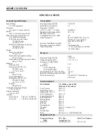
Each radio is capable of operation in 12.5 kHz or 25 kHz
channel spacing systems. System deviation for 12.5 kHz
channel spacing is 2.5 kHz and 5 kHz for 25 kHz channel
spacing.
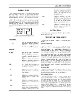
The KPC-300 radio contains three (3) buttons on the front
panel. The KPC-400 contains three (3) buttons along with a
twelve (12) button DTMF pad on the front panel. The scan
function allows monitoring of any or all channels. Any
channel may be scanned with or without a priority level. One
channel can be programmed for Priority 1 (P1) and another
for Priority 2 (P2), with any or all remaining channels
programmed as non-priority channels (S). There is also
Emergency mode transmission capability. A LCD display
provides status display of the radio functions along with the
display of the selected channel number.
The Universal Device Connector (UDC), located on the
side of the radio, provides connections for external audio
accessories. This connector also allows the radio system
personnel to connect programming equipment and program
the per-channel and overall radio features.
Figure 1 - Scan Radio
Figure 2 - System Radio
Figure 3 - Back, Left And Top Panel Views
AE/LZB 119 1874 R1A
5
Summary of Contents for KPC-300
Page 1: ...ericssonz Maintenance Manual KPC 300 400 Portable Radio ...
Page 8: ...Figure 5 Block Diagram AE LZB 119 1874 R1A 8 ...
Page 29: ...EXPLODEDVIEW EXPLODED VIEWS AE LZB 119 1874 R1A 29 ...
Page 30: ...COMPONENT LAYOUT TOP BOTTOM SUB BOARD AE LZB 119 1874 R1A 30 ...
Page 31: ...COMPONENT LAYOUT MAIN BOARD TOP AE LZB 119 1874 R1A 31 ...
Page 32: ...COMPONENT LAYOUT MAIN BOARD BOTTOM AE LZB 119 1874 R1A 32 ...


