

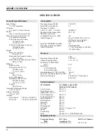


POWER SUPPLY
The battery voltage, provided by six nickel cadmium
cells, is a nominal 7.5 volts. This voltage is provided to the
series regulators via a 4 amp fuse F401. The regulated supply
pr5 volts for the logic section, the analog section,
receiver and transmitter sections. The +5.5 volts for the PLL
frequency synthesizer section is also provided.
RADIO PROGRAMMING
PC PROGRAMMING
The KPC-300/400 Portable Radio is programmed using
an IBM compatible personal computer equipped with a RS-
232 serial port. Adapter TQ-3370 provides the RS-232 serial
interface and the cable between the PC and the adapter box.
Programming Cable RPM 113 2472/1 provides the connec-
tion from the adapter box to the radio’s Universal Device
Connector (UDC). The programming software is AE/LZY
213 761.
PROGRAMMABLE FEATURES
The following features are programmable on a per-chan-
nel basis:
•
Receive Frequency
•
Transmit Frequency
•
Channel Busy Lock-Out
•
Carrier Control Timer (CCT)
•
Squelch Tail Elimination (STE)
•
Fixed Priority 1 Scan Channel
•
Channel Guard Encode/Decode (Tone or Digital)
•
Type 99 Tone Decode
•
Automatic Number Identification (ANI)
•
Telephone Interconnect DTMF Keypad Enable
(KPC-400 only)
The following features are programmable on an overall radio
basis:
•
Display Backlighting
•
Alert Tones
•
Emergency Channel
•
Three (3) Auto-Dial Telephone Numbers (KPC-400
only)
CHANNEL BUSY LOCK-OUT
If channel busy lock-out has been programmed on the
selected channel, the transmit function will be inhibited
when the operator presses the PTT button while the radio
detects a carrier on the channel unless the carrier is modu-
lated with the corresponding Channel Guard tone or code for
that selected channel. The radio will immediately begin
transmitting when the carrier disappears. Channel busy lock-
out continues to function if Channel Guard decode is dis-
abled with the MONITOR button. The channel-busy feature
is programmable on a per-channel basis. Type 99 cannot be
programmed on a channel with channel busy lock-out.
CHANNEL GUARD
Channel Guard (CG) provides a means of restricting calls
to specific radios through the use of Continuous Tone Coded
Squelch System (CTCSS) tone frequencies ranging from
67.0 Hz to 210.7 Hz. Digital Channel Guard (DCG) also can
provide a means of restricting calls through the use of 83
standard Continuous Digital Coded Squelch System
(CDCSS) codes. Each channel may be programmed for en-
code/decode, encode only, decode only or for no CG or DCG.
Both tone frequencies and digital codes may be used. The
tones and codes are listed in Tables 1 and 2.
SQUELCH TAIL ELIMINATION (STE)
STE is used with tone and Digital Channel Guard to
eliminate squelch tails. The STE burst is transmitted when
the microphone PTT is released. The receiving radio decodes
the burst and mutes the receiver audio for 250 ms. This mute
time allows the transmission to end and to eliminate the
squelch tail. The radio looks for STE on the received signal
when the microphone is either on or off-hook. STE is enabled
for transmit and/or receive through PC programming.
AUTOMATIC NUMBER IDENTIFICATION
(ANI)
Automatic Number Identification is a 320 ms burst of
code (GE-STAR) that is generated at the beginning of each
transmission to identify the radio unit to the dispatcher. If
programmed, a beep is sounded at the end of ANI transmis-
sion to indicate when conversation can begin as the micro-
phone is disabled until the ANI transmission is completed.
Systems with CG require that ANI be delayed long
enough for the system to respond before ANI can be decoded.
A programmable delay is provided to meet this requirement.
For example, a delay of 350 ms requires the operator to wait
for 670 ms after pressing the PTT before conversation can be
started. If desired, the ANI message can be programmed to
be sent at the end of a transmission.
AE/LZB 119 1874 R1A
11
Summary of Contents for KPC-300
Page 1: ...ericssonz Maintenance Manual KPC 300 400 Portable Radio ...
Page 8: ...Figure 5 Block Diagram AE LZB 119 1874 R1A 8 ...
Page 29: ...EXPLODEDVIEW EXPLODED VIEWS AE LZB 119 1874 R1A 29 ...
Page 30: ...COMPONENT LAYOUT TOP BOTTOM SUB BOARD AE LZB 119 1874 R1A 30 ...
Page 31: ...COMPONENT LAYOUT MAIN BOARD TOP AE LZB 119 1874 R1A 31 ...
Page 32: ...COMPONENT LAYOUT MAIN BOARD BOTTOM AE LZB 119 1874 R1A 32 ...