


INDICATORS
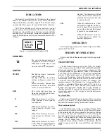
The Liquid Crystal Display (LCD) indicates the channel
number. In addition there are seven (7) status indicators
(flags) which show scan status, Type 99 Tone Decode status,
transmit High/Low power status and Channel Guard status.
The LCD backlighting will turn on anytime a control
button is pressed. It will remain on for five (5) seconds after
the button is released. If a control button is pressed while the
backlight is on, the backlight remains on for another five (5)
seconds. Backlighting may be programmed to remain off at
all times.
CHANNEL
12
The selected channel number is
displayed in the LCD window..
When data is written into or read
from the radio a
P
is displayed.
STATUS
TX LED
Red light on steady - transmitter
is active or keyed.
Red light blinking - low battery
voltage, recharge or replace bat-
tery.
Yellow on steady - channel busy
indication, radio has detected a
carrier on selected channel.
SCN
This status indicator turns on
when the scan function of the ra-
dio has been enabled.
S
When this indicator is on, the se-
lected channel is a non-priority
scan channel.
P1
When this indicator is on, the se-
lected channel is a Priority 1 scan
channel.
P2
When this indicator is on, the se-
lected channel is a Priority 2 scan
channel.
PG
When this indicator is on, the se-
lected channel is programmed as
a paging channel (Type 99 Tone
Decode). The indicator will blink
when the selected channel is
placed in the monitor mode or the
reception of a call.
CG
When this indicator is on, Chan-
nel Guard is enabled on the se-
lected channel. The indicator will
go out when the selected channel
is placed in the monitor mode.
HI
When this indicator is on, the se-
lected channel is enabled for
transmit high power.
OPERATION
Detail operating procedures are found in Operator’s Man-
ual AE/LZT 123 1898.
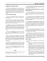
THEORY OF OPERATION
Refer to the Block Diagram during the following expla-
nations.
TRANSMITTER
The transmitter consists of an exciter Q201, PA module
U201, auto power control (APC) U202 with Q202 and Q203,
directional coupler Z201 and associated components. The
local signal input of approximately 0 dBm to the transmitter
is provided by the synthesizer to the exciter. An amplifier
provides 17 dB of gain to p17 dBm (50 mW) of drive
level to the PA module. During the receive mode, a band
switch diode, D202, attenuates the receive first local oscilla-
tor signal at the exciter input to reduce LO leakage at the
antenna connector. The PA module is a 3-stage amplifier that
provides a minimum RF power output of 7.0 watts at a
battery voltage of 7.2 VDC. The RF power output is fed
through the directional coupler Z201 to the antenna. A
shottkey diode D201 converts the detected RF signal in the
directional coupler to a DC voltage to feed the auto power
control circuitry.
Low Pass Filter
The low pass filter Z101 and pi low pass filter, consisting
of L121, C171 and C172, are provided to prevent excessive
transmitter harmonics during the transmit function.
Tx/rx Antenna Switch
The TX/RX antenna switch, consisting of D101, D102
and associated circuitry, provides the switching of RF output
to the antenna and the receive signal to the receiver. During
the receive function, the diodes are cut off, isolating the
transmit circuit from the antenna. During the transmit func-
tion, +5 volts is supplied to both diodes, turning them on and
feeding the RF output from the transmitter PA module
through the low pass filters via D101 to the antenna. The RF
output is suppressed at the receiver RF front end filter by
D102.
SCN HI
S P1 P2
PG CG
Figure 4 - Liquid Crystal Display (LCD)
AE/LZB 119 1874 R1A
7
Summary of Contents for KPC-300
Page 1: ...ericssonz Maintenance Manual KPC 300 400 Portable Radio ...
Page 8: ...Figure 5 Block Diagram AE LZB 119 1874 R1A 8 ...
Page 29: ...EXPLODEDVIEW EXPLODED VIEWS AE LZB 119 1874 R1A 29 ...
Page 30: ...COMPONENT LAYOUT TOP BOTTOM SUB BOARD AE LZB 119 1874 R1A 30 ...
Page 31: ...COMPONENT LAYOUT MAIN BOARD TOP AE LZB 119 1874 R1A 31 ...
Page 32: ...COMPONENT LAYOUT MAIN BOARD BOTTOM AE LZB 119 1874 R1A 32 ...