


EG_GenLoc354e_1040Q_UG_002_UK
Page 45 / 69
Descriptions and non-contractual illustrations in this document are given as an indication only.
ERCOGENER reserves the right to make any modifications.
Dct_427_02
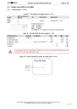
3.18 RESET
The use of the RESET function is strictly reserved for the manufacturer and distributors.
This signal must be used only in case of emergency RESET. A software RESET is always
preferable to a Hardware RESET. It is strongly unadvised to execute this function whilst in
communication or dialog, without having previously detached it from the operator network.
Using the RESET does not restore the factory parameters.
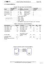
Table 46 : Description of RESET input
16-pin connector
Signal
Pins N°
I/O
Kind of I/O
Description
RESET
GND
10
4
I SCHMITT
Reset
modem
Corresponds to wires
Orange for
RESET
Black for
GND
see ANNEX 4 – 16-pins Micro-FIT cable (16 wires, Serial links,
Boot and Reset)
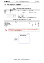
Table 47 : Conditions of use of RESET signal
Parameters
Conditions
Min.
Typ.
Max.
Unit
V
IL
Input Voltage – Low
-0.3
0.8
V
DC
V
IH
Input Voltage – High
2
3.3
V
DC
RIPU
Internal Pull-Up Resistor
5.38K
Ω
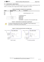
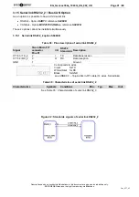
Figure 28 : Internal electrical scheme of RESET
The use of the RESET signal must be done through a transistor assembly or via dry contact .
The integrator has the responsibility to protect the input from electrical perturbations and to
respect the functioning parameters values.
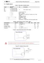
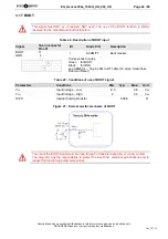
Figure 29 : Chronogram of RESET signal
Summary of Contents for GenLoc 354e
Page 69: ...DECLARATION OF CONFORMITY ...