EG_GenLoc354e_1040Q_UG_002_UK
Page 20 / 69
Descriptions and non-contractual illustrations in this document are given as an indication only.
ERCOGENER reserves the right to make any modifications.
Dct_427_02
Interfaces
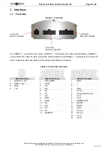
• GSM antenna: connector FAKRA-D
• GNSS antenna: connector FAKRA-C
• Power supply 3.2V for active GNSS antenna
• Power supply: +8 to +32 V
DC
(4-pin micro-FIT connector)
• 1 serial port RS232_0 (300 to 115200bds) Sub-D 9 pins female
• 1 serial port RS232_1 (300 to 115200bds)
• 1 serial link K-Line (ISO 9141-2)
• AT commands : GSM 07.05 and 07.07
- Specific AT commands for GNSS
- SIM reader (SIM 3V – 1,8V)
• 3 opto-coupled inputs
• 2 isolated opto-coupled inputs
• 3 open collector outputs
• 2 analog inputs (0 – 10 Volts)
• 1 power supply output V
POWER
controllable
(16-pin connector micro-FIT)
• Inhibition of the battery charge
• 1 Buzzer output (connector 14 pins micro-FIT)
• Backup battery
• 1 port ONE_WIRE
• Power supply output 4,8 V
• 3-axis accelerometer
Accessories supplied
• Fixing brackets (x2)
• Cables with 4-wire Micro FIT connector (Power supply, Input and Output)
• Cables with 14-pin Micro FIT connector, 14 wires (Input and Output)
• Cables with 16-pin Micro FIT connector, 14 wires (Serial ports)
Options / Additional accessories *
• Bus CAN MCP2515
S0467D
• Double SIM reader
S0471C
• ONE WIRE Multi slaves
S0470C
• 1 serial port RS232_2 RS232C
S0469B
• 2 analog inputs (4 – 20 mA)
S0475C
• Accessories: Antennas, cables, power supplies... (information available on our website)
* These options are in addition or replace some existing options, contact us (see §
* )
Summary of Contents for GenLoc 354e
Page 69: ...DECLARATION OF CONFORMITY ...


