


EG_GenLoc354e_1040Q_UG_002_UK
Page 33 / 69
Descriptions and non-contractual illustrations in this document are given as an indication only.
ERCOGENER reserves the right to make any modifications.
Dct_427_02
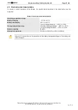
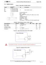
3.7 Opto-coupled inputs
Table 21 : Description of opto-coupled inputs
Signal
Connector
Pins N°
I/O
Description
E1
GND
E2
E4
GND
2 Connector 4 pins
3 Connector 4 pins
12 Connector 14 pins
5 Connector 14 pins
8 Connector 14 pins
I
Digital Inputs 0 – 35 V
Corresponds to wires
Yellow for
E2
Black for
GND
See ANNEX 1 – 4-pins Micro-FIT cable (4 wires, Power
supply)
Corresponds to wires
Brown for
E2
Green for
E4
Black for
GND
See ANNEX 2 - 14-pins Micro-FIT cable (Inputs/Outputs)
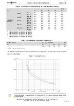
Table 22 : Characteristics of opto-coupled inputs
Characteristics
Symbols
Conditions
Min.
Typ.
Max.
Unit
Max. current
I
F (rms)
50
mA
Max.inverted voltage
V
R
5
V
Direct voltage
V
F
I
F
= 10 mA
1.0
1.15
1.3
V
Inverted current
I
R
V
R
= 5 V
10
µA
Capacity C
T
V=0, f = 1 MHz
---
30
---
pF
Transfer ratio
I
C
/ I
F
I
F
= 5 mA, V
CE
= 5 V
50
---
600
%
Saturation of transfer ratio
I
C
/ I
F (SAT)
I
F
= 1 mA, V
CE
= 0.4 V
60
%
Command voltage
3,5
35
V
Idle voltage
1
V
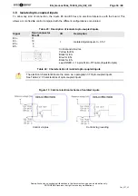
Figure 12 : Internal electrical scheme of opto-coupled inputs
The minimum command voltage for the detection is:
3.5 V
The maximum command voltage is :
35 V
Summary of Contents for GenLoc 354e
Page 69: ...DECLARATION OF CONFORMITY ...