


EG_GenLoc354e_1040Q_UG_002_UK
Page 29 / 69
Descriptions and non-contractual illustrations in this document are given as an indication only.
ERCOGENER reserves the right to make any modifications.
Dct_427_02
3.5 One Wire Bus
3.5.1
One Wire Bus
By default, the One Wire Bus is managed by the processor and only manages « serial number » readers in
read-only mode 64 bits.
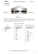
Table 13: One Wire Bus description
Signal
14-pin connector
Pins N°
I/O
Kind of I/O
Description
Bus One Wire
GND
1
I/O
Analog
One Wire Bus
8
Corresponds to wires
White/green
for One Wire Bus
Black
for GND
see ANNEX 2 - 14-pins Micro-FIT cable (Inputs/Outputs)
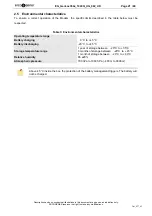
Table 14 : One Wire Bus – Electrical characteristics
Characteristics
Symbols
Conditions
Min.
Typ.
Max.
Unit
Input Voltage – Low
V
IL
-0.3
0.8
V
DC
Input Voltage – High
V
IH
2
3.5
V
DC
Hysteresis Voltage
V
Hys
0.4
0.7
V
DC
Input Leakage Current
I
LEAK
-4
38
µA
DC
Input capacitance
C
IN
14
pF
Output Low-level Voltage
V
OL
0.4
V
DC
Output High-level Voltage
V
OH
2.8
V
DC
Output Current
I
o
±16
mA
DC
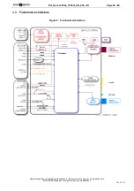
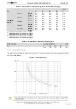
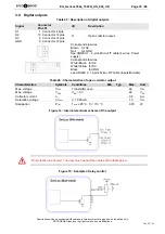
Figure 8 : Internal electrical scheme of the One Wire bus
Assembly working with identification keys DS1990 iButton® from the manufacturer MAXIM.
The integrator has the responsibility to protect the input from electrical perturbations and to
respect the functioning parameters values.
Summary of Contents for GenLoc 354e
Page 69: ...DECLARATION OF CONFORMITY ...