background image

85

Chapter 3    Handling

3

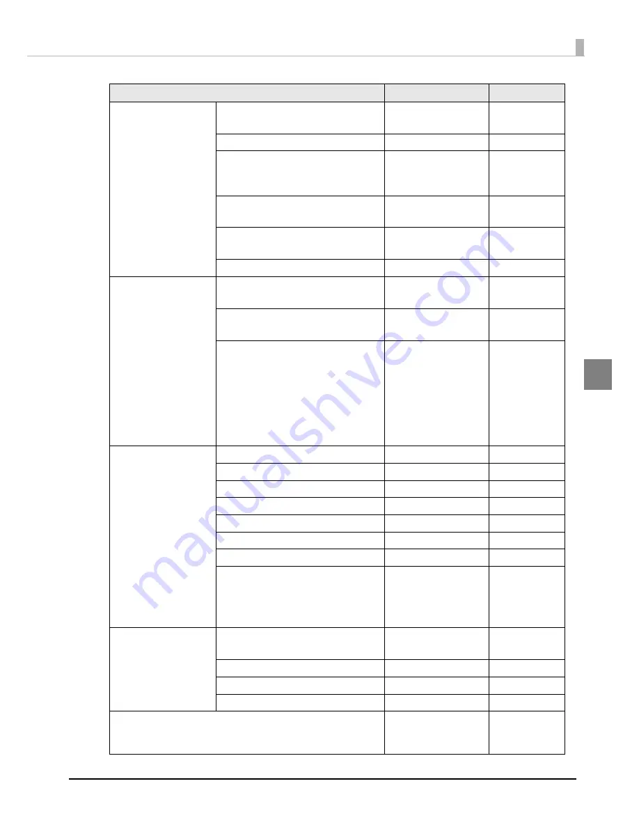
COLOR CONTROLS

MODE

EPSON PREFERRED

EPSON STANDARD

EPSON 

PREFERRED

INK PROFILE

-6 to +4

0

RATIO OF BLACK

-6 to 0

(Available settings 

vary with media type)

0

FEATHER EDGES

ENABLE

DISABLE

DISABLE

DOT SUBSTITUTION

ENABLE

DISABLE

ENABLE

BANDING

-2 to +2

0

MAINTENANCE

CALIBRATION

YES

NO

-

INK RECHARGE

YES

NO

-

PRINT INFO

STATUS BASIC

STATUS SETUP

STATUS NETWORK

LIST FONT

LIST BARCODE

LIST IMAGE

LIST TEMPLATE

-

MAINT. COUNTERS

TOTAL LENGTH

********[mm]

-

LENGTH 1

********[mm]

-

LENGTH 2

********[mm]

-

LABELS 1

********[labels]

-

LABELS 2

********[labels]

-

TOTAL CR

********[motions]

-

TOTAL AUTO CUT

********[motions]

-

FW VERSION

MAIN

NETWORK

FPGA

CG

-

I/F SETUP

IP SETUP

AUTO

MANUAL

MANUAL

IP ADDRESS

***.***.***.***

192.168.192.168

SUBNET MASK

***.***.***.***

255.255.255.000

DEFAULT GATEWAY

***.***.***.***

255.255.255.255

FAVORITE SETTING

The favorite settings 

you have saved will 

be displayed.

-

Settings menu item

Available settings

Default setting

Summary of Contents for TM-C7500 Series

Page 1: ... how to control the printer and necessary information when you develop applications Describes general specifications and character code tables Describes features for the product Technical Reference Guide Series Series M00079105 Rev F Product Overview Setup Handling Application Development Information Appendix ...

Page 2: ...oblems arising from the use of any options or any consumable products other than those designated as Original EPSON Products or EPSON Approved Products by Seiko Epson Corporation Trademarks EPSON is a registered trademark of Seiko Epson Corporation Exceed Your Vision and ESC Label are registered trademarks or trademarks of Seiko Epson Corporation Microsoft Windows Windows Vista and Windows Server ...

Page 3: ...ot cover the product with a cloth or install it in a poorly ventilated location Make sure to allow installation space as specified in this manual Location Appropriate for Installation on page 39 CAUTION Do not install store the product in an unstable location or in a location subject to vibration from other devices Equipment may fall or collapse causing breakage and possible injury Do not install ...

Page 4: ...not modify the power cable Do not place heavy objects on the power cable Do not forcibly bend twist or pull the power cable Do not locate the power plug near a heating device Do not hold the power plug with a wet hand Doing so may cause electric shock Do not connect too many power cables to one outlet Doing so may cause fire Disconnect the power plug from the outlet on a periodical basis and clean...

Page 5: ... that has acquired a safety standard certification and has a power supply system PE terminal Make sure you earth the terminal otherwise it may cause electric shock CAUTION Do not allow anyone to stand or place heavy objects on top of this product Equipment may fall or collapse causing breakage and possible injury Install the cables and optional products in the proper direction according to the pro...

Page 6: ...k cartridges or Maintenance box or supply or replace ink If you disassemble them ink may get into your eyes or adhere to your skin It may also prevent you from printing correctly Ink may leak and damage the printer Do not remodel the ink cartridge Doing so may cause printing malfunction Use of an old ink cartridge may result in reduced print quality Use it up within six months after opening the pa...

Page 7: ...g After installing the ink cartridges be sure to turn the power off using the power button when you are not using the product Do not pull out the power plug or trip the breaker while the power is on Printing on water repellent paper such as art paper which is slow drying may cause print stains Also printing on glossy paper may cause finger prints on the paper or ink may adhere to your fingers when...

Page 8: ...Caution Label The caution label on the product indicates the following precaution CAUTION Take care not to injure your fingers on the fixed blade of the autocutter autocutter blade autocutter fixed blade ...

Page 9: ...plications requiring extremely high reliability safety such as aerospace equipment main communication equipment nuclear power control equipment or medical equipment related to direct medical care etc please make your own judgment on this product s suitability after a full evaluation About this Manual Aim of the Manual This manual was created to provide information on development design and install...

Page 10: ...nual 9 Manual Content 9 Contents 10 Product Overview 15 Features 15 Printing 15 Operability 16 Reliability 16 Easy setup 16 How to Print 16 Other Features 17 Part Names and Functions 18 Front Side 18 Operation Panel 19 Rear Side 21 Nozzle Verification Technology 22 Setting the Nozzle Verification Technology 22 Dot substitution 24 Periodic auto cleaning 25 Status Error Indications 26 Ink Cartridge ...

Page 11: ...the Maintenance box 47 REWINDER 50 How to install the REWINDER 50 Removing the rewinder 51 Attaching the paper leading edge to the rewinder 52 Setting the Paper 54 Setting the Roll Paper 54 Setting the Fanfold Paper 62 How to eject paper for paper replacement 63 Ejection Angle of Printed Paper 64 Printer settings 65 Language Setting 65 Time Setting 66 Network settings 67 Paper settings 69 Set usin...

Page 12: ...Settings save and restore 113 Option 114 Setting the Printer Driver 115 Favorite Setting 115 User Defined Information 118 Exporting Importing Printer Driver Settings 118 Barcode Printing 121 2D symbol Printing 131 Barcode and 2D Symbol Font Printing on NET Environment 138 Banding Reduction 140 Start the PrinterSetting from the printer driver 141 Setting EPSON Status Monitor 3 142 Restricted items ...

Page 13: ...r Driver 163 Poor print quality 164 Unclean media 167 Printable area 167 Detection failure 168 External supply 168 Paper is jammed 169 Application Development Information 173 How to Control the Printer 173 Using label printing application 173 Using the Epson Inkjet Label Printer SDK 174 Using the ESC Label commands 174 Changing Printer Settings and Replacing the Printer 175 Software and Manuals 18...

Page 14: ...cations for the Number of Printed Copies 213 Display While Printing 213 Error Display While Printing 213 Display When the Number of Printed Copies is Carried Up to 8 digits 213 Downloading Drivers Utilities and Manuals 214 Media detector and paper path settings when using label printing applications215 Changing the media detector settings in BarTender 216 Changing the paper path settings in BarTen...

Page 15: ...pi x 1200 dpi dpi dots per 25 4 mm dots per inch Supporting diverse media types Supports 8 inch diameter roll paper and fanfold paper Supports full page labels with black mark and die cut labels Supports the gap between labels and blackmark position detection TM C7500 Series Supports plain labels matte labels and synthetic labels TM C7500G Series Supports the plain labels matte labels synthetic la...

Page 16: ...asily setup a printer driver install software or perform media settings and settings of this product How to Print A Windows printer driver that can be used with Windows applications is available For the label printing applications listed below we provide dedicated drivers for the TM C7500 TM C7500G series By installing these drivers you can easily use all of the functions of the TM C7500 TM C7500G...

Page 17: ...ndard Can be used as a local printer of a computer or network printer The auto cutter is equipped by default Paper can be cut by a command from applications or panel switch operations A beeper is equipped by default Notifications are available for no media or low ink error end of printing etc In case of a USB printer because new print cues are generated when the damaged printer is replaced with ot...

Page 18: ...er Open this cover to remove jammed paper Rewinder Connection Cover Open this cover to install the rewinder option Maintenance Box Cover Open this cover to install replace the maintenance box Roll Paper Cover Open this cover to set roll paper Paper Set Cover Open this cover to set roll paper or fanfold paper Ink Cartridge Cover Operation Panel Front Cover Rewinder Connection Cover Maintenance Box ...

Page 19: ...Lights in the following conditions The ink cartridge cover maintenance box cover is open No ink cartridge maintenance box is set It is time to replace the ink cartridge maintenance box LCD Displays the menus and messages See Ink Cartridge and Maintenance Box Status on page 31 Pause Button Press this button during printing to pause printing after one page of data is printed Press this button while ...

Page 20: ...enu Button Use this button to select menus and items OK Button Executes the selected menu and item Cut Button Cuts the paper Feed Button Press this button for less than three seconds to feed one page of paper Press this button for three seconds or more to feed the paper continuously Back Feed Button Press this button only when replacing paper After cutting the printed paper using the Cut button ho...

Page 21: ...4 or more from the air vent to ensure ventilation when installing the product Dip Switch Cover mounting screw Remove the screw to open the Dip Switch Cover Dip Switch Used when changing the function of the Power button Dip Switch Cover When operating the Dip Switch remove the Dip Switch Cover Mounting Screw and open the cover When setting the Power button operation to Power switch disabled Reset o...

Page 22: ...ill be performed Starting a printing job or per printed sheets specified in the interval of Nozzle check interval Power is turned ON The maintenance box cover is closed The roll paper cover or paper set cover is closed after a paper jam If the number of nozzle dropouts that is detected exceeds the Threshold of clogged nozzles that you have set auto head cleaning will be executed to eliminate dot d...

Page 23: ...et in the unit of pages from 1 to 500 See Setting panel switch on page 82 or PrinterSetting on page 89 Setting Threshold of clogged nozzles Set the allowable number of nozzle dropouts when executing a Nozzle Verification Technology When the number of nozzle dropouts exceeds the value a head cleaning is executed If the number of clogged nozzles does not reach this value the dot substitution functio...

Page 24: ...ed After that printing can continue This function does not become enabled even when setting the dot substitution to enable if the Nozzle Verification Technology is disabled Settings It can be set from the setting menu of this product and PrinterSetting The factory setting is On See Setting panel switch on page 82 or PrinterSetting on page 89 This function does not completely remedy falls in print ...

Page 25: ...o cleaning If periodic auto cleaning implementation time setting is disabled periodic auto cleaning will be implemented at a time that the printer judges necessary for example when a fixed time has elapsed since the previous periodic auto cleaning If the power is off at the time you set the periodic auto cleaning will be implemented the next time the power is turned on Periodic auto cleaning may s...

Page 26: ...ter the power is turned ON EPSON TM C For 2 to 4 seconds after the power is turned ON The model name is displayed on LCD INITIALIZING 4 seconds after the power is turned ON and until the printer switches to the idling status The LCD displays the remaining level of ink and the available amount of space in the maintenance box POWER OFF Performing the powering off process During this time do not forc...

Page 27: ...g is interrupted and print data inside the printer are deleted PRINTING NOZZLE CHECK DISABLED Nozzle Verification Technology is disable When dot dropouts cannot be detected due to low environmental temperature the LCD display shows a message Printing continues NOZZLE CLOGGED Unrecoverable nozzle dropouts happen This display is shown when unrecoverable nozzle dropouts happen Printing continues NOZZ...

Page 28: ...e and set the media detector MEDIA FORM ERROR Media form error The media type settings of the printer and the media in the printer are different button can be used to move to the setting mode and set the media type NO PAPER No paper No paper is available MEDIA SIZE ERROR Media size error The media size settings of the printer and the size of the media in the printer are different NO PAPER ERROR No...

Page 29: ...R EMPTY Ink level low The level of ink indicated in the LCD display is low and ink cartridges need to be changed soon Printing is possible INK CARTRIDGE EMPTY Ink cartridge needs to be replaced The ink cartridges indicated in the LCD display need to be changed Check the target ink on the LCD screen INK CARTRIDGE READ ERROR Ink cartridge CSIC error The ink cartridge information could not be read NO...

Page 30: ...en creating a file that exceeds the available size of this product s built in storage SD built in RAM SERVICE REQUIRED SOON The product is near the end of its service life The maintenance service of the printer is due soon Printing is possible SERVICE REQUIRED The product is beyond its service life Malfunction Printer maintenance is necessary No printing can be performed PRINTER ERROR Fatal error ...

Page 31: ...ink cartridge Display of amount used for the maintenance box Display for Ink cartridge low Display for Maintenance box near full Display for Replace ink cartridge Display for Replace maintenance box Display for No ink cartridge Display for Ink cartridge read error Display for No maintenance box Display for Maintenance box read area Amount used for the maintenance box Amount remaining for the ink c...

Page 32: ...conds Until the error factor is removed Service required Printer error Replace ink cartridge Replace maintenance box Media form error Media size error Paper jam error Paper removal error Paper out error 100 ms 100 ms 5 1 second 1 Ink cartridge cover open Maintenance box cover open Paper set cover open Roll paper cover open Front cover open Auto loading failure Storage capacity over No ink cartridg...

Page 33: ...fore using this product This product can be set up using the following methods Perform setup following the Install Navi on the included CD ROM page 34 Use the computer to start the Install Navi on the included CD ROM and follow the procedure to set up this product Setup this product without using the Install Navi page 36 ...

Page 34: ...rt the CD ROM in your computer and the Launcher automatically starts Click Printer Setup to start the Install Navi 4 When the Install Navi is executed the following screen is displayed Agree to the SOFTWARE LICENSE AGREEMENT and click Next Follow the instructions on the screen from here on to setup this product One of the setup steps of Install Navi is Software installation in which printer driver...

Page 35: ... Chapter 2 Setup 2 See the following if you are installing the rewinder How to install the REWINDER page 50 Attaching the paper leading edge to the rewinder page 52 This completes the setup of the product ...

Page 36: ...nt after setup you want to use 3 Connecting the Power Cable page 40 2 Installing the Printer page 38 1 Checking the Items Included in the Package page 37 4 Connecting the Interface Cable page 41 5 Installing the Ink Cartridge page 43 8 Attaching the paper leading edge to the rewinder page 52 7 Setting the Paper page 54 9 Printer settings page 65 10 Paper settings page 69 11 Test printing page 76 C...

Page 37: ...tems included in the package The items included in the package are as follows 1 It can be used for initial ink charging 2 This is required when re shipping the product Keep it in a safe place A TM C7500 Series B Ink cartridge C M Y K 1 C CD ROM D USB cable E Roll paper F AC cable G Cushioning material 2 A B C D E F G ...

Page 38: ...t Doing so may cause an accident When transporting this printer do not put it upside down or topple over sideways Do not place anything that weighs more than 10 kg on top of the printer The printer may be damaged if an excessive force is applied Do not install the printer at a high location where it may fall during operations Do not install the printer at a location that is subject to vibration or...

Page 39: ...r side of the product In a location free of vibration and impacts In a location where a dedicated power outlet is available In a location where you can set and remove paper without difficulty In a location with sufficient space around the product to allow for installation of accessories replacement of consumable products and daily cleaning In a location meeting the following conditions Temperature...

Page 40: ...oduct securely to the bottom 2 Fully insert the power plug securely into the outlet WARNING Use only AC 100 V for the power supply Using other type of power supply may cause electric shock or fire Be sure to install this product in the vicinity of a power outlet so that you can immediately unplug the product if some fault or other problem occurs ...

Page 41: ...ing the Interface Cable Connect the interface cable to be used to the connector on the rear side of the printer CAUTION When using a USB cable pass the cable through the wire saddle to prevent accidental disconnection Wire Saddle ...

Page 42: ...tion describes how to turn on off the product Turning On 1 Press Power button 2 Power LED lights up and the power turns on Turning Off 1 Hold down Power button for one second or more 2 Power LED turns off and the power turns off ...

Page 43: ...elow 1 Turn on the product 2 Open the ink cartridge cover 3 Shake the ink cartridge package four or five times before opening it CAUTION Read the handling instructions carefully before installing the ink cartridge See Cautions on the Ink Cartridge Maintenance box on page 6 or Ink Cartridge on page 211 ...

Page 44: ... the ink cartridges of the four colors gently into the product until they click in place Check the color of the ink cartridge label and of the ink cartridge holder label and set the cartridges to each matching color ...

Page 45: ...ct during ink charging while the Power LED is flashing Doing so during ink charging will consume a large amount of ink which may require replacement of the ink cartridge before completion of charging The ink cartridge included in the product package is used for initial charging The printer uses ink to prepare for printing when the ink cartridge is installed for the first time It takes at least 10 ...

Page 46: ...e Change to an ink cartridge with enough ink level using the following steps 1 Check that the Ink LED is ON Also check the ink cartridge to be replaced with the LCD display 2 Open the ink cartridge cover 3 Push the ink cartridge to be replaced slowly After making sure that its lock is unlocked pull the ink cartridge out toward you 4 Shake the ink cartridge package four or five times before opening...

Page 47: ...the ink level in the ink cartridge becomes low Ink LED flashes and MB NEAR FULL is displayed on the LCD When MB NEAR FULL is displayed prepare to replace the maintenance box The number of papers that can be printed before status changes from MB NEAR FULL to REPLACE MB depends on usage conditions CAUTION Read the handling instructions carefully before installing the Maintenance box See Cautions on ...

Page 48: ... on LCD and the product changes to offline Change to a Maintenance box with enough space using the following steps 1 Check that the INK LED on the printer is lit up and check that the maintenance box displays REPLACE MAINT B on the LCD 2 Open the maintenance box cover towards you 3 Pull out the used maintenance box towards you ...

Page 49: ...new maintenance box gently in with its labeled surface upward 6 Close the maintenance box cover 7 When the maintenance box replacement is completed the INK LED turns off and printing can be performed 8 The product goes into the pause state Push the Pause button to release it and the product returns to the idle state ...

Page 50: ...rewinder with the following steps 1 Open the rewinder connection cover on the front of the printer 2 Insert the rewinder s power transmission gear into the cover opening Make sure that the mark at the bottom of the rewinder is aligned with the plate edge ...

Page 51: ...51 Chapter 2 Setup 2 Removing the rewinder Pull the rewinder s lever in the direction of the arrow below and remove the rewinder from the printer ...

Page 52: ... Attach the paper to the rewinder with the following steps 1 Remove the rewinder s flange 2 Press the Feed button and bring out approx 800 mm 31 50 of paper from this product 3 Pass the paper under the roller and onto the rewinder as in the figure below ...

Page 53: ...the rewinder flange roughly 2 rotations to take up the slack paper If no roll core is used Insert the paper leading edge into the slot in the rewinder s spindle then turn the rewinder flange roughly 2 rotations to take up the slack paper 5 Install the rewinder flange Do not forget to install the rewinder flange Bulging and other winding abnormalities will occur if the flange is not installed ...

Page 54: ...54 Setting the Paper Setting the Roll Paper Set the roll paper by following the steps below 1 Turn on the product 2 Open the paper set cover 3 Open the roll paper cover ...

Page 55: ...e while holding the release lever of the roll paper flange between your fingers 5 Attach the roll paper to the spindle and push the core of the roll paper as far as possible so that it is securely fit it into place Roll Paper Flange Release Lever Spindle ...

Page 56: ...auto feeding in the step 12 to go smoothly 7 Attach the roll paper flange to the spindle while holding the release lever of the roll paper flange between your fingers Push the flange to the bottom to align it with the roll paper width 300 mm About Roll Paper Flange Release Lever ...

Page 57: ...per guide a Align the end of the paper with mark CAUTION Check to make sure there are no deformities such as folds rips wrinkles or peeling in the edge of the paper If you insert paper that is deformed it could cause improper paper feeding misaligned printing or paper jams Paper Hold Paper Guide a Mark ...

Page 58: ...around Move the paper guide b to align it with the paper width while pushing the paper guide b lever 11Adjust the guide panel of the paper guide b so that it aligns perfectly with the edge of the paper Lever Paper Guide b Guide panel Paper Guide b ...

Page 59: ... set properly If the Paper LED stays on the paper is not set properly Set the paper again CAUTION If the guide panel does not match the paper width it could cause misaligned printing or paper jams Be careful of the following Do not allow a gap to occur between the guide panel and the edge of the paper Do not press the guide panel strongly against the edge of the paper Paper Feed Slot ...

Page 60: ...he paper guide b and the edge of the paper Paper will be fed properly with this gap After closing the paper hold check if there is a gap between the guide panel and the edge of the paper If there is no gap it might cause misaligned printing or paper jams Return to step 8 Paper Hold 0 02 0 5mm Edge of the paper Guide panel paper guide b Gap ...

Page 61: ...1 Chapter 2 Setup 2 14If the paper is loose turn the roll paper flange in the direction of the arrow to tighten the paper 15Close the roll paper cover 16Close the paper set cover 17Press the Pause button ...

Page 62: ...r 3 Set the fanfold paper referring to Step 8 to 12 in Setting the Roll Paper 4 Close the paper set cover 5 Place the fanfold paper straight 15 mm or more away from the rear side of the product Also for the paper width direction match it to the standard marking on the rear side of the product 6 Press the Pause button 15 mm 0 59 ...

Page 63: ...utton for 1 second or longer 4 Open the paper set cover 5 Open the paper guide s two paper hold levers and remove the paper In the case of fanfold paper that completes paper ejection 6 In the case of roll paper open the roll paper cover and take the flange off 7 While holding the release lever of the roll paper flange pull out the roll paper flange Then pull the roll paper out Paper Hold ...

Page 64: ...the label being pulled into the printer is clear to the printer user In such a case if you want to carry out an operation that involves handling the ejected paper such as setting it in the rewinder press the Pause button to stop printer operation before carrying out the operation Similarly if you need to separate the fanfold paper along its perforated line by hand press the Pause button to stop pr...

Page 65: ...ssages displayed on the LCD by following the steps below 1 Turn on the product 2 Press the Menu button to display the menu 3 Select PRINTER SETUP3 and press the OK button 4 Select LANGUAGE and press the OK button 5 Select the language to be used The following languages are available Japanese English French German Dutch Italian Spanish Portuguese 6 Press the OK button This completes language settin...

Page 66: ... 2 Press the Menu button to display the menu 3 Select PRINTER SETUP3 and press the OK button 4 Select CLOCK and press the OK button 5 Enter the current date and time Use the button to select a number and the buttons to select the item to be changed 6 Press the OK button This completes time setting ...

Page 67: ...en MANUAL is selected go to Step 7 and set IP address etc 7 Select IP ADDRESS and press the OK button 8 Enter the IP address Use the button to select a number and the buttons to select the digit to be changed When using the product with an Ethernet connection it is necessary to setup the network When using with a USB connection network settings are not necessary When performing network settings ob...

Page 68: ...ter the Subnet mask For the input method refer to the input of the IP address in Step 8 12Press the OK button 13Select DEFAULT GATEWAY and press the OK button 14Enter the Default gateway For the input method refer to the input of the IP address in Step 8 15Press the OK button ...

Page 69: ...er on page 69 When not using a Windows driver See Setting using the PrinterSetting on page 72 When setting up in an environment not connected to a computer See Setting with the operation panel on page 75 Set using a printer driver 1 Turn on the product 2 Display the printer driver window See How to Display the Printer Driver on page 78 3 Click Media Detection ...

Page 70: ...dia source and Media Detection and click OK 5 Click User Defined 6 The User Defined Media Layout screen is displayed 7 Enter Media Layout Name If there is an existing defined media layout you can create a new layout based on the defined media layout 8 Select Media Form ...

Page 71: ... This completes the settings of media source media coating type media form and media detection When enlarging the print area put a checkmark in Borderless Printing to eliminate margins When the margins are zero the print may extend outside of the media label Use it accordingly When Borderless Printing is checked Feather Edges can be checked When Feather Edges is checked gradation processing is per...

Page 72: ...PrinterSetting 1 Turn on the product 2 Start PrinterSetting See Starting the PrinterSetting on page 90 3 The Media settings screen is displayed 4 Set the Media source Media detection Media coating type Click Apply settings ...

Page 73: ...ft select Layout settings Click Edit layout 6 The User Defined Media Layout screen is displayed 7 Enter Media Layout Name If there is an existing defined media layout you can create a new layout based on the defined media layout 8 Select Media Form ...

Page 74: ...tings This completes the settings of media source media coating type media form and media detection When enlarging the print area put a checkmark in Borderless Printing to eliminate margins When the margins are zero the print may extend outside of the media label Use it accordingly When Borderless Printing is checked Feather Edges can be checked When Feather Edges is checked gradation processing i...

Page 75: ...9 Select media form and click the OK button Select one from DIE CUT LABEL CONT LABEL CONT PAPER 10Select LEFT GAP and click the OK button 11Specify the left gap pixels and click the OK button The settable range is 0 to 2551 pixels 12Select LABEL WIDTH and click the OK button 13Specify the label width and click the OK button Settable range is 0 to 2551 pixels 14Select LABEL LENGTH and click the OK ...

Page 76: ...press the OK button The nozzle check pattern is printed 5 Check the printed nozzle check pattern If the pattern is printed normally all the lines are printed properly as shown in the left figure below The nozzle is clogged if there is an unprinted line as shown in the right figure below Perform head cleaning if this occurs Depending on the settings for the threshold of clogged nozzles the clogged ...

Page 77: ... View devices and printers of Control Panel on Start menu For Windows Vista Click Printers of Control Panel on Start menu For Windows XP Professional Click Printers and Faxes on Start menu For Windows XP Home Edition Click Control Panel on Start menu and click Printers and Faxes For Windows Server 2003 R2 Click Printers and Faxes on Start menu 2 Right click EPSON TM C7500 and click Printer propert...

Page 78: ...nu For Windows Vista Click Printers of Control Panel on Start menu For Windows XP Professional Click Printers and Faxes on Start menu For Windows XP Home Edition Click Control Panel on Start menu and click Printers and Faxes For Windows Server 2003 R2 Click Printers and Faxes on Start menu 2 Right click EPSON TM C7500 and click Printing References The printer driver screen is displayed Registered ...

Page 79: ...in Top margin Bottom margin Printing position adjustment longitudinal Printing position adjustment lateral Printing speed Change of Monochrome Color Resolution Adjustment font width Head maintenance Operations after printing Cutoff position adjustment Paper feed amount adjustment Printing of paper feed adjustment pattern Nozzle Verification Technology Nozzle check interval Operation when nozzle dr...

Page 80: ...le Ratio of black to composite Edge shading Nozzle dropout supplementation Banding reduction Calibration Ink recharging 1 Printer data printing Printing distance non resettable display Printer distance resettable counter 1 display Printer distance resettable counter 2 display Labels printed count resettable counter 1 display Labels printed count resettable counter 2 display Cumulative carriage mot...

Page 81: ...nding on the condi tions 2 It is a different function from Favorite setting of the Printer Driver The two functions are not compatible When using the Printer Driver use Favorite of the Printer Driver ink Subnet mask Default gateway Selection of character code tables Registration of fonts images and templates Setting preset images Enable Disable of Operation Panel Cancel Feed and Cut Paper feed adj...

Page 82: ...RNAL FEED INTERNAL ROLL LEFT GAP 0 to 2 551 pixel 47 LABEL WIDTH 0 to 2 551 pixel 2 551 LABEL LENGTH 0 to 14 173 pixel 3 600 LEFT MARGIN 0 to 35 pixel 35 RIGHT MARGIN 0 to 35 pixel 35 TOP MARGIN 0 to 35 pixel 35 BOTTOM MARGIN 0 to 35 pixel 35 V POSITION 48 to 48 pixel 0 H POSITION 24 to 24 pixel 0 PRINTING SPEED 150 mm s 300 mm s 150 mm s RESOLUTION 600 dpi 300 dpi 200 dpi 600 dpi HEAD MAINTENANCE...

Page 83: ...0 to 500 sheets 0 sheets OPERATION AT CLOGGED NOZZLE CONTINUE NOTIFY CONTINUE THRESHOLD OF CLOGGED NOZZLES 0 to 10 nozzles 6 REPRINT ENABLE DISABLE ENABLE POWER ON ACTION FEED CALIBRATION NO FEED FEED PAPER CHANGE ACTION FEED CALIBRATION NO FEED FEED CANCEL ACTION JOB ONLY JOB RAM DRIVE JOB ONLY SCHEDULED CLEAN ENABLE DISABLE DISABLE CLEANING TIME HH MM 24 hour clock 00 00 Settings menu item Avail...

Page 84: ...ANGUAGE JAPANESE ENGLISH FRENCH GERMAN ITALIAN SPANISH PORTUGUESE DUTCH According to market destination CLOCK MM DD YY HH MM CONTROL PREFIX 0x00 to FF 0x7E FORMAT PREFIX 0x00 to FF 0x5E DELIMITER CHAR 0x00 to FF 0x2C FACTORY RESET YES NO ERASE MEMORY YES NO INITIALIZE I F YES NO INITIALIZE MEDIA DETECTION SENSOR YES NO Settings menu item Available settings Default setting ...

Page 85: ...ES NO PRINT INFO STATUS BASIC STATUS SETUP STATUS NETWORK LIST FONT LIST BARCODE LIST IMAGE LIST TEMPLATE MAINT COUNTERS TOTAL LENGTH mm LENGTH 1 mm LENGTH 2 mm LABELS 1 labels LABELS 2 labels TOTAL CR motions TOTAL AUTO CUT motions FW VERSION MAIN NETWORK FPGA CG I F SETUP IP SETUP AUTO MANUAL MANUAL IP ADDRESS 192 168 192 168 SUBNET MASK 255 255 255 000 DEFAULT GATEWAY 255 255 255 255 FAVORITE S...

Page 86: ...RINT INFO and press the OK button 5 Select STATUS NETWORK and press the OK button The product will print out the status sheet Network settings A status sheet Network settings printout sample HHHH Epson Status Sheet HHHH General Information MAC Address Software Network Status TCP IP IPv4 Obtain IP Address IP Address Subnet Mask Default Gateway xx xx xx xx xx xx xxxxxxxxx AUTO Disconnected Manual xx...

Page 87: ...bled when printing with TM C7500 TM C7500G Series printer drivers You can use this function with the product firmware Ver WAI30000 or later or with PrinterSetting Ver 1 2 0 0 or later Instructions for use 1 In PrinterSetting save the Favorite setting settings to the product See Saving favorite settings on page 108 2 Make sure that the printer is not in the middle of the cleaning operation or print...

Page 88: ...he Troubleshooting section remove the error and configure Favorite setting again You can select Favorite setting on the operation panel or in PrinterSetting If the settings could not be configured PRINTER IS BUSY CHANGE FAILED will appear for 3 seconds Check the printer status again and reconfigure the settings The application settings will be given priority over the settings in Favorite setting o...

Page 89: ...adjustment Adjusts the print start position or cut position page 96 Print results adjustment Adjusts the color preset or the barcode page 98 Store data in the printer Register images templates and fonts to the printer Also select a code to use from the character code table page 99 Background image settings Sets a preset image page 100 Print head maintenance Perform a print head maintenance or nozz...

Page 90: ...ll Programs Epson TM C7500 Series PrinterSetting 3 The Select printer screen is displayed Select a search target and click Search 4 This product is displayed in the list Select a printer to set and click OK For an Ethernet connection the product may not be displayed when a search is executed In that case enter IP address ...

Page 91: ...91 Chapter 3 Handling 3 5 Start the PrinterSetting ...

Page 92: ...92 Apply settings After setting each item click Apply settings to change the settings of this product ...

Page 93: ...ction settings Media source Sets the media source Media detection Sets the media detection method Print settings Media coating type Sets the media type Paper feed adjustment Adjusts the paper feed Printing performance Printing speed Sets the printing speed Head maintenance Sets the head maintenance mode when printing For the head maintenance mode during printing refer to Printing speed on page 188...

Page 94: ...dia layout This setting screen is not displayed if you started PrinterSetting from the printer driver Item Description Layout settings Media layout Sets the media layout Edit layout Creates a new user defined media layout When clicked the Layout settings screen is displayed ...

Page 95: ...ng When checked the printing range can be expanded When the margins are zero the print may extend outside of the media label Use it accordingly Feather edges When Feather edges is checked gradation processing is performed on the margin areas It can be set only when Borderless printing is checked When printing on long labels depending on the media the printing result may not reach the spec ified le...

Page 96: ...ts the print start position in the vertical direction Click Start adjustment to adjust the position Print start position adjustment Horizontal direction Adjusts the print start position in the horizontal direction Click Start adjustment to adjust the position Cut position adjustment Adjusts the cut position Click Start adjustment to adjust the position ...

Page 97: ...g the print start position adjustment vertical direction as an example 2 Enter the adjustment value and click Apply settings 3 The confirmation screen is displayed Click Yes to execute the adjustment 4 The results are displayed Click OK 5 After executing the adjustment perform printing and check the adjusted position ...

Page 98: ... Mode Sets the color correction method Ink profile Sets the ink concentration Depending on the media in use adjust accordingly to secure the print quality Ratio of black to composite Sets the ratio of black to composite Banding reduction Sets when banding reduction is necessary Adjust barcode Bar width adjustment Set if you are adjusting the bar width when using the embedded barcode font ...

Page 99: ... and character code tables to the printer Item Description Image Only png Registers an image used for preprinting or templates Template Registers a template Font Only ttf and tte Registers a font to apply to print data Character code table Changes the character code used for printing ...

Page 100: ... screen is not displayed if you started PrinterSetting from the printer driver Item Description Set background image Do not use background image The preset image is not printed Use shared background image In case of regular printing print the specified image as a preset image When printing using a template the preset image is not printed Use different background images for each template When print...

Page 101: ...r on page 99 Also specify a preset image in Background image settings on page 100 Printing the preset image The preset image is printed in the following cases When using the Windows driver from Zebra Technologies Corporation When using the commercially available label printing application that supports this product When using an application that directly controls ZPL II or ESC Label commands The p...

Page 102: ... a nozzle check Nozzle check Prints nozzle check patterns and checks clogged nozzles Click Start to start printing the nozzle patterns Specified time for print head maintenance Any time as needed When periodical cleaning is necessary the cleaning operation will be performed immediately Only at specified time When periodical cleaning is necessary the cleaning operation will be performed at the spec...

Page 103: ...placement action Sets the action when the paper is replaced Operations after printing Sets if the media should be cut after printing Notification settings Beeper volume Sets the beeper volume Ink low LED Sets the action when the ink level becomes low Error settings Sets the reprint action when an error occurs Set time Sets the date and time of the product ...

Page 104: ...button settings Cancel button Enables disables the Cancel button Feed button Enables disables the Feed button Cut button Enables disables the Cut button LCD settings LCD brightness Sets the LCD brightness LCD contrast Sets the LCD contrast Language Sets the language of the LCD display ...

Page 105: ...f clogged nozzles The standard setting is 0 Additional auto nozzle check during printing Sets the additional auto nozzle check during printing Nozzle check interval Sets the nozzle check interval for when executing the additional auto nozzle check during printing Operations when clogged nozzle detected Dot substitution Enables disables the dot substitution Operation at clogged nozzle Sets the oper...

Page 106: ...tings from printer using ZPL II commands Replace settings from printer using ZPL II commands Performs replacing settings from the printer using ZPL II commands Click Set to display the Replace settings from printer using ZPL II commands screen Set prefix text Sets the prefix text Set Printer s Favor ite Settings Here you can save the favorite settings to the product or apply the saved favorite set...

Page 107: ... then set Use in Monochrome Print Mode to ON Click Apply settings 3 The confirmation window is displayed Click Yes to reflect the settings 4 The result is displayed Click OK When you click Default settings the entered value returns to the printer s default value When you click Apply settings the settings return to the printer s default settings Adjust the font width while actually printing Regardi...

Page 108: ... window appears Enter the Favorite Settings Name and configure Printer s Favorite Settings After you have configured the settings click Set If you click Load printer settings the settings that have already been configured for this product will be loaded The save name of the Favorite setting can include 15 ASCII characters 20h 7Eh except for and You can save up to 100 items in Favorite setting ...

Page 109: ...be displayed in Stored data Applying favorite settings Here you can apply the saved favorite settings to the product 1 Click Select the Favorite Settings in Set Printer s Favorite Settings 2 The Select Printer s Favorite Settings window appears Select the favorite settings you wish to apply in Favorite Settings Name and click Apply settings ...

Page 110: ...110 Initialize printer Initializes the printer Item Description Initialize Factory reset Initializes the printer to the factory settings Erase memory Initializes the extended memory ...

Page 111: ...inter information Item Description Printer information Printer settings list When View is clicked the settings information of the current printer is displayed Refer to Printer settings list on page 112 Maintenance counters The maintenance counters can be checked ...

Page 112: ...112 Printer settings list When View of the printer settings list is clicked the Printer settings list screen is displayed Click Output to file to save the current settings to a text file ...

Page 113: ... save the data in File name Specify a file name Start saving After specifying the data to be saved a folder to be saved and file name click Start saving and the settings of this product are saved Restore settings Backup file Specifies a backup file File data Displays the information of a backup file Start restoring After specifying a backup file click Start restoring to restore the settings of the...

Page 114: ...at the start Item Description Display settings Units Sets the units Startup Settings Display a welcome screen at startup Initializes the expanded memory Unit settings are only for PrinterSetting They are not reflected on the operation panel or the printer driver ...

Page 115: ...to one The setting from General and Options tab such as Media Coating Type Media Layout including User Defined Media are included Favorite setting of the printer driver is different from Favorite setting of the product The two functions are not compatible It cannot be combined with Favorite setting of the product General tab Options tab Favorite Setting ...

Page 116: ...icking Save as Favorite Setting A number of setting can be registered on Favorite Setting For example if the print setting is registered on Favorite Setting for each document the print setting can be completed by changing Favorite Setting when the document is changed This prevents an error of setting change when changing the paper It is necessary to change Media position detection of the printer w...

Page 117: ...4 Click Save The print setting will be registered in Favorite Setting the Save Delete Favorite Setting screen will close and you will return to the original screen Favorite Setting includes the following setting Default Settings The default setting when installing the printer driver Current Settings The contents set on General and Option tab These contents are displayed in the current settings on ...

Page 118: ...BSF file to set up the printer driver Export Settings Follow the steps below to export the settings 1 Check that the print setting has been registered in Favorite Setting If multi ple print settings are registered the print setting located first on the Favorite Setting will be reflected when importing the settings Favorite setting of the printer driver is different from Favorite setting of the pro...

Page 119: ...file from the current settings If you export it from the general setting a dif ferent content will be exported Current settings Properties of the printer driver General Printing References Driver Utilities Import Export Settings General setting Properties of the printer driver Advanced Printing Defaults Driver Utilities Import Export Settings To the BSF file the print settings in favorite setting ...

Page 120: ...rs Click OK 4 The window to open a file appears Select the file to be imported 5 The process completion window appears Click OK When the settings are imported from a BSF file the printer driver settings are overwritten There fore to retain the existing settings for the items listed below create a BSF including the existing settings Favorite List User Defined Media List Barcode Font List Barcode Fo...

Page 121: ...es tab 1 Change settings of the following Display Select Barcodes Font Name Input an arbitrary character string ASCII characters only Type Select a barcode type from the following The displayed items are changed accordingly Rotation Settings Select a setting when printing the barcode rotated by the specified rate UPC A UPC E JAN13 EAN JAN8 EAN Code39 ITF Codabar NW7 Code93 Code128 GS1 128 GS1 Data...

Page 122: ...tio is 2 5 Check Digit Values or marks appended to prevent sequential number errors or fabrication Auto Convert to Minimize Entire Symbol Width Selectable when CODE128 is specified This function minimizes the number of symbol characters required to express the given data string Start Character Sets a start character End Character Sets an end character 2 Click Add The selected barcode font is saved...

Page 123: ...on Plain label Barcode type Printing direction Minimum Module by 600 dpi ANSI Grade C or higher ANSI Grade B or higher Code39 Fence 5 7 Ladder 6 8 Codabar NW7 Fence 5 6 Ladder 6 8 Code93 Fence 5 7 Ladder 6 8 Code128 GS1 128 Fence 5 6 Ladder 6 7 ITF Fence 6 8 Ladder 6 7 GS1 DataBar Omnidirectional GS1 DataBar Truncated Fence 6 6 GS1 DataBar Limited GS1 DataBar Expanded Ladder 6 8 UPC A UPC E Fence ...

Page 124: ...igher Code39 Fence 5 6 Ladder 5 6 Codabar NW7 Fence 5 6 Ladder 5 6 Code93 Fence 5 6 Ladder 5 6 Code128 GS1 128 Fence 5 6 Ladder 5 6 ITF Fence 6 6 Ladder 6 6 GS1 DataBar Omnidirectional GS1 DataBar Truncated Fence 6 6 GS1 DataBar Limited GS1 DataBar Expanded Ladder 6 6 UPC A UPC E Fence 7 7 JAN13 EAN JAN8 EAN Ladder 7 7 The recognition rate for the barcode varies depending on the media type barcode...

Page 125: ...AN JAN8 EAN Ladder 7 7 The recognition rate for the barcode varies depending on the media type barcode reader s performance and so on The barcode rank may decline due to missing dots or curving on the ink drops making the barcode unreadable by the barcode reader Thus we recommend that you try printing HRI characters and so on Ink may penetrate the paper due to its characteristics and bars of print...

Page 126: ...igits The check digit is automatically added UPC E Specify data in 10 digits 5 digits are a manufacturer code and the rest 5 digits are an item code JAN13 EAN Specify data in 12 digits The check digit is automatically added JAN8 EAN Specify data in 7 digits The check digit is automatically added Code39 When both or either one of start stop code is not specified it is automatically added ITF When d...

Page 127: ...erefore it is not necessary to specify a code selection character from an application While the code selection character CODE A is selected if A is specified to select CODE A an error occurs While the code selection character CODE B is selected if B is specified to select CODE B an error occurs While the code selection character CODE C is selected if one of the following is specified an error occu...

Page 128: ...orrectly an error occurs A special character is indicated by combining and the next character When the character right after is not any of the following an error occurs Control Character ASCII HRI Character SHIFT S Not printed CODE A A Not printed CODE B B Not printed CODE C C Not printed FNC1 1 Not printed FNC2 2 Not printed FNC3 3 Not printed FNC4 4 Not printed is printed Control Character ASCII...

Page 129: ...ure to include all the application identifiers in the data When the first data is 01 after deleting application identifiers left and right parenthesis and from the specified data the 14th digit from the next of 01 is checked as a check digit When it is not correct an error occurs When the next data of 01 is fewer than 14 digits a check digit is not checked Unlike GS1 128 the check digit is not aut...

Page 130: ...lue The barcode is not printed when other values are selected Some applications such as the NET application may not be able to display or select a barcode font registered by the printer driver In that case if you use the font replacement function to replace the True Type font with the barcode font you can print barcodes See Barcode and 2D Symbol Font Printing on NET Environment on page 138 ...

Page 131: ...code and 2D Symbol Settings on Driver Utilities tab 1 Change settings of the following Display Select 2D Symbols Font Name Input an arbitrary character string ASCII characters only Type Select a 2D symbol type The displayed items are changed accordingly Rotation Settings Select a setting when printing the 2D symbol rotated by the specified rate Hexadecimal Input Mode Turn on the check box when the...

Page 132: ...le Height Makes settings of the module height for MicroPDF417 by the ratio to the module width Recommended value of the module on page 134 for the recommended value Column Input the number of columns for MicroPDF417 Step Enter the number of steps for MicroPDF417 QRCode Model Select a QRCode model Module Select the width of cell module for QRCode Recommended value of the module on page 134 for the ...

Page 133: ...on area with a percentage value in the input box DataMatrix Symbol Shape Set when Rectangle is selected for the sample shape of DataMatrix Error Correction Level Select an error correction level for DataMatrix Cell Size Select the width of cell module for DataMatrix Recommended value of the module on page 134 for the recommended value Number of Vertical Cells Specify the number of cells for DataMa...

Page 134: ...er PDF417 5 5 MicroPDF417 5 6 GS1 DataBar Stacked GS1 DataBar Stacked Omnidirectional GS1 DataBar Expanded Stacked 5 5 2D symbol type Minimum Module by 600 dpi ANSI Grade C or higher ANSI Grade B or higher PDF417 5 5 MicroPDF417 5 5 GS1 DataBar Stacked GS1 DataBar Stacked Omnidirectional GS1 DataBar Expanded Stacked 5 5 2D symbol type Minimum Module by 600 dpi ANSI Grade C or higher ANSI Grade B o...

Page 135: ...0 12 Micro QR Code 12 12 AztecCode 8 9 DataMatrix 8 10 Maxi Code 21 21 2D symbol type Minimum Module by 600 dpi ANSI Grade C or higher ANSI Grade B or higher QR Code 10 11 Micro QR Code 12 12 AztecCode 8 9 DataMatrix 8 9 Maxi Code 21 21 2D symbol type Minimum Module by 600 dpi ANSI Grade C or higher ANSI Grade B or higher QR Code 9 11 Micro QR Code 11 12 AztecCode 8 9 DataMatrix 7 9 Maxi Code 21 2...

Page 136: ... the following format DataMatrix When data are if the following does not apply to the data immediately after an error occurs GS1 DataBar Stacked GS1 DataBar Stacked Omnidirectional Do not specify the application identifier 01 for the head of the data A check digit need not to be attached to the data When printing a 2D symbol with a composite symbol delimit the data that specify a composite symbol ...

Page 137: ... full range mode and the compact mode Printing method Specify the selected 2D symbol font specified point and language to the printing data and print it The font size of the 2D symbol can not be changed by Specified Point value The 2D symbol is not printed when other values are selected Some applications such as the NET application may not be able to display or select a 2D symbol font registered b...

Page 138: ...Barcode and 2D symbol fonts can be printed from the application under NET Framework environment by this replacement function The name of the print data in the application remains as True Type font name but changes to barcode and 2D symbol font when it is printed Font Replacement Font Replacement is executed from Font Replacement on Driver Utilities tab 1 Make the following setting Replacement True...

Page 139: ...ode and 2D symbol is specified check it from Barcode and 2D Symbol on Driver Utilities The barcode and 2D symbol can not be printed if a value other than those specified is set The replaced True Type font can be used only for specifying barcode and 2D symbol therefore if the character other than specified is used can not be printed Make sure to use True Type font that is not be used for other prin...

Page 140: ...The setting value of Banding Reduction is inappropriate on page 165 Follow the steps below to reduce banding 1 Display the printer driver window See How to Display the Printer Driver on page 78 2 On General window select Advanced under Print Settings Then click Advanced 3 Advanced screen appears Check Banding Reduction and click Close 4 The screen returns to General window Click OK ...

Page 141: ... Start the PrinterSetting from the printer driver with the following steps 1 Display the printer driver window See How to Display the Printer Driver on page 78 2 Select Printer Utility tab Click Printer Setting Utility 3 The TM C7500 Series PrinterSetting screen is displayed ...

Page 142: ...s Monitor 3 Not use EPSON Status Monitor 3 is set by default setting Notification Settings for Fatal Errors is displayed on the EPSON Status Monitor 3 Settings window in Driver Utilities Follow the steps below to change to Use EPSON Status Monitor 3 1 Turn the printer ON 2 Display the printer driver window See How to Display the Printer Driver on page 78 3 Select Driver Utilities tab and click Dri...

Page 143: ...window automatically appears allowing you to check the printer status and the ink level Error information is displayed when an error occurs during printing The EPSON Status Monitor 3 will not be activated if an error occurs when not printing Clicking the icon for EPSON Status Monitor 3 on the task tray allows you to display EPSON Status Monitor 3 at any time See Displaying the icon on page 147 for...

Page 144: ... set in Monitoring preferences Selecting error indications See Error notification setting for Not use EPSON Status Monitor 3 on page 145 Displaying the EPSON Status Monitor 3 icon on the task bar See Displaying the icon on page 147 ...

Page 145: ...atus Monitor 3 is enabled Notification Settings for Fatal Errors is not dis played Disable Use Not use EPSON Status Monitor 3 on page 142 4 The Notification Settings for Fatal Errors window is displayed Select the items you want to display when an error occurs and click OK Ambient Temperature Error When the printer temperature is high Default Screen Notification On Service Required When a no print...

Page 146: ...yed Enable EPSON Status Monitor 3 by referring to Use Not use EPSON Status Monitor 3 on page 142 4 The Monitoring Preferences window is displayed Select the items you want to display when an error occurs and click OK Error When paper ink replacement is required Default Screen Notification On Communication Error When the printer power is off Default Screen Notification Off Ink Low When the ink amou...

Page 147: ...ng Follow the steps below to display the icon 1 Turn the printer ON 2 Display the printer driver window See How to Display the Printer Driver on page 78 3 Select Driver Utilities tab and click Monitoring Preferences 4 The Monitoring Preferences window is displayed Check the box of Shortcut Icon and select the icon to display on the task bar Click OK ...

Page 148: ...first When printing multiple jobs while Print spooled documents first is enabled the print execution order and output order vary When using an Epson printer driver leave the control prefix format prefix and delimiter settings of ESC Label command as default When changed printing may not be performed or unintended printing may occur For the default values refer to page 82 in PRINTER SETUP3 of Panel...

Page 149: ...placed if the printer driver is specified There is no need to change the USB serial number of the product before replacement Uninstallation of USB Printer Class Device Replacement Service USB Printer Class Device Replacement Service is not displayed in the software list in the control panel For uninstallation follow the steps below 1 Close all applications running on the computer 2 Select Start Co...

Page 150: ...indicating default printer in Devices and Printers window may be shown on the previous printer that was applied before replacement Or the check mark may not appear In these cases the check mark indication can be corrected with the following steps Return to the desktop screen and open Devices and Printers window again Right click the printer driver and select Set as default printer Log off the user...

Page 151: ...od and so the reprinting will print one or more depending on the length of the labels used unfinished pages in which printing by some of the heads only is completed Reprinting is carried out in units of pages If an error that is the cause of reprint is cleared by canceling the job printer reset or power on off the printer does not perform reprint Paper feed direction Printer Not included in reprin...

Page 152: ... cover turn the product off Otherwise a short circuit may cause the product to malfunction DIP switch settings are enabled only when the power is turned on If the settings are changed after that the functions will not change SW ON OFF Initial setting 1 Power button Disabled Reset operation Power button Enabled Power ON OFF operation OFF 2 Forbidden Do not change setting OFF 3 Reserved Do not chang...

Page 153: ...l paper cover and remove the paper See How to eject paper for paper replacement on page 63 3 Remove the adhesive on the autocutter fixed blade of the roll paper cover side with a cotton swab Slightly moisten the cotton swab with alcohol if necessary How to Clean the Case When cleaning the printer case use absorbent cotton dampened with ethanol for disinfection or isopropyl alcohol if necessary WAR...

Page 154: ...nter in a cool 0 to 25 C 32 to 77 F and dark place CAUTION If dot missing has occurred ink may clot inside the nozzle to cause nozzle clogging making it difficult for the printer to recover from the problem when the printer restarts Dot missing may occur especially after transporting the printer from the place where it is used to the place where it is stored due to vibration CAUTION When powering ...

Page 155: ...head cleaning automatically 3 Run a nozzle check print and check whether dot missing or any other print ing problems have occurred In the cases listed below replace the ink cartridge See Installing the Ink Cartridge on page 43 2 years has passed since the ink cartridge was manufactured 6 months has passed since the ink cartridge was opened CAUTION Do not turn the product off or do not open Ink car...

Page 156: ...e media When transporting the product do not remove the ink cartridge or maintenance box When transporting the product turn the power OFF using the Power button and place it in the designated packing box When transporting this product use the included cushioning material in the procedure below Step 1 Open the ink cartridge cover Step 2 Place the cushioning material in the ink cartridge cover Step ...

Page 157: ... to that is suitable for the loaded paper The type of the paper set in the printer is different from the specified media type on the label printing application or the printer driver provided by the label printing application manufacturer Set the type of paper specified on the label printing application or the printer driver provided by the label printing application manufacturer to that is suitabl...

Page 158: ...PER OUT ERROR Paper out error Paper has run out during printing If any paper remains in the paper path remove it Then set new paper in place PAPER PATH ERROR Paper path error The paper supply method for the paper set is different from the method specified in the Media supply method settings Set paper in place that is appropriate for the Media supply method settings or change the Media supply metho...

Page 159: ...over is open Close the roll paper cover PAPER COVER OPEN Paper set cover open The paper set cover is open Close the paper set cover FRONT COVER OPEN Front cover open The front cover is open Close the front cover INK COVER OPEN Ink cartridge cover open The ink cartridge cover is open Close the ink cartridge cover NO INK CARTRIDGE No ink cartridge An ink cartridge is not loaded 1 Open the ink cartri...

Page 160: ...ance box cover 2 Load a maintenance box with sufficient space 3 Close the maintenance box cover M B READ ERROR Maintenance box read error The maintenance box information could not be read 1 Open the maintenance box cover 2 Remove the maintenance box 3 Load the maintenance box again 4 Close the maintenance box cover 5 If the error occurs again replace the maintenance box with a new one REPLACE INK ...

Page 161: ...ff and on again 4 Remove all the paper that is in the paper path 5 Close the front cover 6 Turn the power back on If the error occurs again request a repair 7 Run auto loading of the paper ERR B2 This error may occur if you run Paper feed adjustment Mech wear using PrinterSetting when print data is left in the product When this error occurs turn the product off and back on Also when running Paper ...

Page 162: ...ot be permitted perform repairs CUT UNAVAILABLE In cutter unavailable state Autocutting is being performed 2 or more times with the paper in the same position Execute paper feed or printing operation To prevent occurrence of paper scraps do not execute auto cutting two or more times without feeding the paper SERVICE MODE In service mode The product is in the mode for performing repairs and inspect...

Page 163: ... Port setting of the driver properties is disabled When using an printer driver enable the Enable the bi direction support in the Port setting of the properties When using a ZPL II compatible printer driver with this product printing may not be performed Check whether printing is possible by using the latest version of the ZPL II compatible printer driver ...

Page 164: ... Coating Type setting is different from the media that is actually used The Media Coating Type setting of the printer driver may be different from the media used Check the Media Coating Type setting of the printer driver and the media used For details refer to Paper settings on page 69 Paper feeding adjustment is necessary Depending on the media uneven printed colors may occur due to changes in th...

Page 165: ... on page 140 Also if the Nozzle Verification Technology in Nozzle check settings is disabled change to enabled default Roll paper is not set properly For the roll paper open the roll paper cover and reset the media correctly For details refer to Setting the Roll Paper on page 54 Fanfold paper is not set properly For the fanfold paper leave it 15 mm or more from the rear side of the printer and pla...

Page 166: ...ia Coating Type setting of the printer driver may be different Check the media used and the printer driver s Media Coating Type For details refer to Paper settings on page 69 Bar width adjustment is not performed To perform appropriate barcode printing the bar width adjustment must be done for the print data When using the printer driver select Advanced in Print Settings under the General tab of t...

Page 167: ... This is the specification of the product When using the printer driver and Borderless Printing is not enabled in User Defined Media Layout and Media Layout The area where 1 5 mm margins on the top bottom right and left are excluded from the label size is the printable area When making the whole label size as the printable area enable Borderless Printing When Borderless Printing is enabled printin...

Page 168: ... Also recognition may be possible by Automatic adjustment of gap and blackmark detection sensor Start the PrinterSetting from the printer driver Select Detailed settings and Advanced settings and execute Adjust media detection sensor For details refer to Advanced settings on page 106 The sensor is damaged If it had been working properly the sensor may be damaged Request a repair State Cause Recove...

Page 169: ... not forcibly pull out paper that is jammed but rather remove it by following the steps below 1 Make sure that the product is powered off 2 Open the paper set cover 3 Pull the front cover open lever at the paper feed slot Front Cover Open Lever ...

Page 170: ...170 4 Open the front cover 5 Cut the jammed paper and remove it WARNING Do not touch the metal wheels Doing so may cause injury ...

Page 171: ...71 Chapter 3 Handling 3 6 Pull out the paper from the paper feed slot 7 Close the front cover 8 Set the paper again See Setting the Paper on page 54 CAUTION Ink may adhere and your fingers may get dirty ...

Page 172: ...172 ...

Page 173: ...ations of application Controlling method Page Use the label printing application and the printer driver provided by the label printing application manufacturer Use the label printing application and the printer driver of the label printing application manufacturer page 173 Print using the printer driver installed in the setting up flow in Chapter 2 Uses the Printer driver page 115 Print from the c...

Page 174: ...gramming interface for the Epson s printer driver By using the EPDI the Epson s printer driver settings can be performed from application soft ware the customer is developing For explanation of the EPDI and required technical information to use in an application program refer to the EPDI for Inkjet Label Printer Refer ence Manual that comes with the SDK EpsonNet SDK The EpsonNet SDK provides an AP...

Page 175: ... page 21 or Connecting the Interface Cable on page 41 When you set the monochrome print mode preset images will be color Connect this product to a computer used for settings USB Interface Connect this product to the computer used for settings via a USB cable Ethernet Interface Connect this product to the network Setting the USBInformationSetting Overwriting the USB ID Setting the IP Address Use Ep...

Page 176: ...acing Perform the following procedure 1 From the Start menu select Epson then TM C7500 Series and click USBInformationSetting 2 USBInformationSetting starts up Set the replacement method then click Next Item Description Replacement method Select Auto setup When you select Auto setup the USB ID and other information is automatically acquired from the printer before replacing and set ...

Page 177: ...settings via USB and turn on the printer s computer Click Next 4 The information of the printer you have been using until now is acquired Before connecting this printer unplug the printer you have been using until now 5 Connect the computer used for settings to this product via USB and turn on the power of this product Click Next ...

Page 178: ...ode Use the PrinterSetting to set the printer s resolution based on the resolution of the printer using ZPL II commands Also set your printer to monochrome print mode For the setting method see Replace settings from printer using ZPL II commands on page 107 Registering Preset Images Use the PrinterSetting to register preset images Registering images Set the images to be used in preset printing See...

Page 179: ...f the printed item you can use PrinterSetting to perform adjustment Display the Replace settings from printer using ZPL II commands window and adjust the font width For the method to display the Replace settings from printer using ZPL II commands window see Replace settings from printer using ZPL II commands on page 107 If you want to change the height of characters or the space between lines perf...

Page 180: ...b USB Printer Class Device Replace ment Service Service installed as a resident program on the computer When the product is replaced for service or other reason this detects the printer connection and automatically changes the output printer of the printer driver This allows the printer to be replaced without changing settings in the application The printer is not replaced if a port is specified f...

Page 181: ... the first time and charging ink Included with the product Ink Cartridge Instruction Sheet Describes cautionary items regarding ink Ink cartridge with the rewinder Maintenance Box Instruction Sheet Describes cautionary items and the replacement procedure for the Maintenance box Maintenance box with the rewinder TU RC7508 User s manual Describes cautionary items and the installation procedure for t...

Page 182: ...tware installation procedures Install the software using the following steps 1 Turn on the computer 2 Check that the product s power is OFF 3 Insert the CD ROM in your computer and the Launcher automatically starts Click Install Software 4 The following screen is displayed Place a checkmark on the installation software and click Next The selected software is installed Make sure the printer s power...

Page 183: ...driver Add this product with the following steps 1 Install the printer driver 2 Turn on the product 3 Open the Devices and Printers See How to Display the Printer Driver on page 78 4 Execute Add a printer and add the product following the instructions on the screen In the printer driver installation screen that is displayed during the procedure select Epson as the manufacturer and EPSON TM C7500 a...

Page 184: ...184 ...

Page 185: ...abel Synthetic label Glossy label Media form Full page label Black mark Die cut label Gap Die cut label Black mark Media source Roll paper Fanfold paper Ink cartridge See Ink Cartridge on page 211 for details 4 color ink separated exclusive ink cartridge Interface Ethernet 1000BASE T 100BASE TX 10BASE T USB 2 0 high speed Barcode two dimensional code printing Barcode UPC A UPC E JAN13 EAN JAN8 EAN...

Page 186: ...0 F 5 to 85 RH no condensation 20 C or 60 C 4 or 140 F up to 120 hours Ink loaded 20 to 40 C 4 to 104 F 20 C 4 F up to 120 hours 0 to 25 C 32 to 77 F up to 6 months 40 C 104 F up to a month Overall dimensions H x W x D 392 x 598 x 395 mm 15 43 x 23 54 x 15 55 excluding protrusions Weight mass Approximately 37 0 kg 81 57 lb Not including the ink cartridge maintenance box and roll paper ...

Page 187: ...rver 2012 Windows Server 2008 Windows Server 2003 Computer equipped with Pentium 4 2GHz or better processor is recommended Intel Pentium Celeron series or AMD Athlon Duron family processor or processor interchangeable with these is recommended Memory Conforms to the operating environment of the OS For Windows 8 1 Windows 8 Windows 7 Windows Vista Windows XP Windows Server 2012 Windows Server 2008 ...

Page 188: ...25 Fanfold paper Minimum 46 mm 1 81 Maximum 108 mm 4 25 During printing Head maintenance mode Input resolution 1 width x length Graphic resolution 1 width x length Flushing on paper Maximum Printing speed 2 Average printing speed 3 Continuous Printing 600 x 600 dpi 600 x 1200 dpi Standard 300 mm s 11 81 s 150 mm s 5 91 s 300 mm s 11 81 s 150 mm s 5 91 s Pause for Maintenance Intermittent printing ...

Page 189: ...ontaminated or the paper may jam Do not use the paper which is extended by connecting with tape and others The paper may be detected incorrectly by the connected line and rubbed by the print head and become contaminated or the paper may jam Media form Media type Media source Width Full page label Black mark Plain label Matte label Synthetic label Roll paper 50 mm to 112 mm 1 97 to 4 41 Backing pap...

Page 190: ...46 to 108 mm 1 81 to 4 25 Label width Die cut label Gap Plain label Matte label Synthetic label Glossy label Roll paper 50 mm to 112 mm 1 97 to 4 41 Backing paper width 46 to 108 mm 1 81 to 4 25 Label width Die cut label Black mark Plain label Matte label Synthetic label Glossy label Roll paper Fanfold paper 50 mm to 112 mm 1 97 to 4 41 Backing paper width 46 to 108 mm 1 81 to 4 25 Label width ...

Page 191: ...ck marks 25 4 to 603 mm 1 to 23 74 Paper thickness Plain label matte label synthetic label 0 129 to 0 236 mm 0 005 to 0 009 reference values Glossy label 0 167 to 0 182 mm 0 007 to 0 007 reference values Paper core Internal diameter 76 2 0 5 mm 3 0 020 External diameter 82 2 mm 3 24 or more External diameter Maximum 203 2 mm 8 Winding direction Printing face must be facing outside Do not use the p...

Page 192: ...tic label 0 129 to 0 236 mm 0 005 to 0 009 reference values Glossy label 0 167 to 0 182 mm 0 007 to 0 007 reference values Paper core Internal diameter 76 2 0 5 mm 3 0 020 External diameter 82 2 mm 3 24 or more External diameter Maximum 203 2 mm 8 Winding direction Printing face must be facing outside Do not use the paper with a hole or cutout If the backing is synthetic paper or film it will be d...

Page 193: ...abels Edge cutoff Edge cutoff Label width When removing all the fringes Black mark position Black mark width Mark length Gaps between Black marks Black mark position when paper is inserted upside down Paper feed direction Label area Backing paper Perforated line 2 mm or more Fanfold paper 0 08 Back side Printing side ...

Page 194: ... 5 mm 0 20 or more Black mark position Right edge of back of paper when feed edge is at top Gaps between black marks 28 4 to 606 mm 1 12 to 23 86 Paper thickness Plain label Matte label 0 129 to 0 236 mm 0 006 to 0 009 reference values Glossy label 0 167 to 0 182 mm 0 007 to 0 007 reference values Paper core Internal diameter 76 2 0 5 mm 3 0 020 External diameter 82 2 mm 3 24 or more External diam...

Page 195: ...to 0 006 reference value Perforated line pitch 203 2 to 304 8 mm 8 to 12 Form of perforated line 1 mm 0 039 uncut 5 mm 0 20 cut Number of folds 750 or less Do not use the paper with a hole or cutout Autocutting on the perforated lines may generate minute paper dust causing machine prob lems Also autocutting ahead of the perforated line may cause problems when feeding paper Therefore autocutting mu...

Page 196: ... for the backing paper and 23 or lower for the labels When using paper with black marks the black mark reflectance rate must be 10 or lower and the white reflectance rate is 70 or higher When preprinting on the back of the continuous paper do not preprint on the area where preprinting is prohibited that is shown in the figure below to avoid affecting paper detection 15 mm 13 mm Paper feed directio...

Page 197: ...k leading edge must be at least 1 5 mm 0 06 If it is less than 1 5 mm 0 06 the printer may be unable to print pages because it fails to sense their black marks or skips them etc Black mark position Paper Label area Print area Auto cut position Auto cut position Print area width Paper width Paper feeding direction 1 5 mm 0 06 1 5 mm 0 06 1 5 mm 0 06 1 5 mm 0 06 25 4 mm or more 1 0 28 mm or more 1 1...

Page 198: ... protrude out ensure mar gins of 1 5 mm 0 06 or more in the print data The distance from the paper cut position to the black mark leading edge must be at least 1 5 mm 0 06 If it is less than 1 5 mm 0 06 the printer may be unable to print pages because it fails to sense their black marks or skips them etc Black mark position Paper Label area Print area Auto cut position Auto cut position Print area...

Page 199: ... Label area Print area Print area width Auto cut position Auto cut position Perforated line Paper width Paper feeding direction Outer edge Removed 2 0 mm 0 08 Outer edge Removed 2 0 mm 0 08 1 5 mm 0 06 1 5 mm 0 06 25 4 mm or more 1 0 28 4 mm or more 1 12 22 4 mm or more 0 88 1 5 mm 0 06 1 5 mm 0 06 1 5 mm 0 06 1 5 mm 0 06 0 5 to 1 mm 0 02 to 0 04 Interval between labels 3 0 mm 0 12 ...

Page 200: ...osition and the set position for the paper label To make sure printing doesn t protrude out ensure margins of 1 5 mm 0 06 or more in the print data Black mark position Label area Print area Print area width Auto cut position Auto cut position Perforated line Paper width Paper feeding direction Outer edge Removed 2 0 mm 0 08 Outer edge Removed 2 0 mm 0 08 25 4 mm or more 1 0 28 4 mm or more 1 12 1 ...

Page 201: ...he printer may be unable to print pages because it fails to sense their black marks or skips them etc Print area width Auto cut position Auto cut position Auto cut position Perforated line Paper width Paper feeding direction Black mark position Paper Label area Print area 25 4 mm or more 1 0 28 4 mm or more 1 12 22 4 mm or more 0 88 1 5 mm 0 06 1 5 mm 0 06 0 5 to 1 mm 0 02 to 0 04 1 5 mm 0 06 1 5 ...

Page 202: ... 06 or more in the print data The distance from the paper cut position to the black mark leading edge must be at least 1 5 mm 0 06 If it is less than 1 5 mm 0 06 the printer may be unable to print pages because it fails to sense their black marks or skips them etc Black mark position Paper Label area Print area Print area width Paper width Paper feeding direction Auto cut position Auto cut positio...

Page 203: ... between the issuing pitch Pm and the interval of perforated lines Ph is as follow Pm Ph x integral multiple Auto cut position Auto cut position Perforated line Auto cut position Perforated line Paper width Paper feeding direction Black mark position Paper Label area Print area Print area width Issuing pitch Ph Interval of perforated lines Pm Outer edge Removed 2 0 mm 0 08 Outer edge Removed 2 0 m...

Page 204: ...er cut position to the black mark leading edge must be at least 1 5 mm 0 06 If it is less than 1 5 mm 0 06 the printer may be unable to print pages because it fails to sense their black marks or skips them etc Black mark position Paper Label area Print area Print area width Paper width Paper feeding direction Issuing pitch Ph Interval of perforated lines Pm Auto cut position Auto cut position Perf...

Page 205: ...1 1 A Frequency rated 50 Hz to 60 Hz Power consumption Operating 100 V Average Approximately 84 W Peak Approximately 123 W 230 V Average Approximately 81 W Peak Approximately 102 W Idling 100 V Average Approximately 5 1 W 230 V Average Approximately 5 4 W When power is OFF 100 V Average Approximately 0 2 W 230 V Average Approximately 0 5 W Use the dedicated AC cable included in the product package...

Page 206: ...ull page label Synthetic 500 km Full page label Glossy 500 km Autocutter mechanism TM C7500 Die cut label backing Plain 1 500 000 cuts Die cut label backing Matte 1 500 000 cuts Die cut label backing Synthetic 500 000 cuts Full page label Plain 750 000 cuts Full page label Matte 200 000 cuts Full page label Synthetic 100 000 cuts TM C7500G Die cut label backing Plain 1 500 000 cuts Die cut label b...

Page 207: ...ely 0 to 2 500 m above sea level approximately 0 to 98425 20 Not operating including in transportation 700 to 1060 hPa approximately 0 to 2 500 m above sea level approximately 0 to 98425 20 Vibration resistance When packed Frequency 5 to 55 Hz Acceleration Approximately 19 6 m s2 2 G Sweep 10 minutes half cycle Time 1 hour Orientation x y and z Shock resistance When packed Packing Epson standard p...

Page 208: ...208 External Dimensions Main unit outline drawings Width 392 mm 15 43 Depth 598 mm 23 54 Height 395 mm 15 55 Unit mm 395 15 55 392 15 43 21 7 0 85 638 25 12 598 23 54 ...

Page 209: ...209 Appendix When Covers are Open Unit mm 632 5 24 90 691 2 27 21 717 6 28 25 ...

Page 210: ...210 When Rewinder is Installed Option TU RC7508 Unit mm 900 35 43 958 37 72 ...

Page 211: ... to the printer 2 years after manufacturing Temperatures Transport 20 to 60 C 4 to 140 F up to 5 days for 60 C 140 F Storage 20 to 40 C 4 to 104 F up to a month for 40 C 104 F Installation 20 to 40 C 4 to 104 F up to a month for 40 C 104 F The expiration date of 2 years after the date of manufacture is printed on the individual box containing the ink cartridge and on the ink cartridge itself Ink i...

Page 212: ...ion Specifications Rewinder TU RC7508 The rewinder is a device used to rewind the printed paper into a roll form Overall dimensions H x W x D 293 x 222 x 403 mm 11 54 x 8 74 x 15 87 Weight mass 4 25 kg 9 37 lb ...

Page 213: ... of printed copies are displayed alternately at intervals of one second at the bottom row Error Display While Printing If printing is paused due to an error the error condition is displayed at the upper row and the ink indicator and the number of printed copies are displayed alternately at intervals of one second at the bottom row Display When the Number of Printed Copies is Carried Up to 8 digits...

Page 214: ...rs utilities and manuals can be downloaded from one of the following URLs For customers in North America go to the following web site http www epsonexpert com For customers in other countries go to the following web site https download epson biz com service pos ...

Page 215: ... detector settings in NiceLabel page 219 Changing the paper path settings in NiceLabel page 221 Changing the media detector settings in CODESOFT page 222 Changing the paper path settings in CODESOFT page 223 These configuration instructions are for the following version of the label printing applica tion In other versions the functions or configuration methods may differ BarTender BarTender Enterp...

Page 216: ...rTender You can change the media detector settings in BarTender by following the steps below 1 Open a BarTender document btw Select Page Setup in the File menu 2 The Page Setup window appears Select the Media Handling tab and click Driver Settings ...

Page 217: ...ange Media Type in Media Settings and click OK Driver Settings of the corresponding operation panels Media Type MEDIA DETECT MEDIA FORM Gap Die cut Label GAP DIE CUT LABEL Mark Die cut Label BLACK MARK DIE CUT LABEL Mark Continuous Paper BLACK MARK CONT PAPER Mark Continuous Label BLACK MARK CONT LABEL ...

Page 218: ...age Setup window appears Select the Media Handling tab and click Driver Settings 3 The Epson Colorworks C7500 Printing Preferences window appears Select the Stock tab and click Advanced under Media Type 4 The Advanced Media Settings window appears Change Media in Media Type and click OK Driver Settings of the corresponding operation panels Media MEDIA SOURCE Internal INTERNAL ROLL External EXTERNA...

Page 219: ...Label by following the steps below 1 Open a NiceLabel label lab Select Label Setup in the File menu 2 The Label Setup Wizard window or the Label Setup window appears Select Epson TM C7500 for NiceLabel and click Properties If you check the Do not use the wizard next time box the Label Setup window appears ...

Page 220: ...age Setup and click OK Driver Settings of the corresponding operation panels Media type MEDIA DETECT MEDIA FORM Labels with black mark BLACK MARK DIE CUT LABEL Labels with gaps GAP DIE CUT LABEL Continuous label with mark BLACK MARK CONT LABEL Continuous paper with black mark BLACK MARK CONT PAPER ...

Page 221: ...ct Label Setup in the File menu 2 The Label Setup Wizard window or the Label Setup window appears Select Epson TM C7500 for NiceLabel and click Properties 3 The Epson TM C7500 for NiceLabel Printing Preferences window appears Change Media form and click OK Driver Settings of the corresponding operation panels Media form MEDIA SOURCE Roll INTERNAL ROLL Fanfold EXTERNAL FEED ...

Page 222: ...s in CODESOFT by following the steps below 1 Open a label file lab Select Label Page Setup in the File menu 2 The Label Page Setup window appears Select Label Change Media and click OK Driver Settings of the corresponding operation panels Media MEDIA DETECT With gap GAP Marked BLACK MARK ...

Page 223: ... Open a label file lab Select Label Page Setup in the File menu 2 The Label Page Setup window appears Click Settings 3 The Printer settings EPSON TM C7500 window appears Change Media source and click OK Driver Settings of the corresponding operation panels Media source MEDIA SOURCE Internal roll INTERNAL ROLL External feed slot BLACK MARK ...

Page 224: ...andard Personal Product name Ver None Your application information Windows service operation Normal EXE operation EPSON application status EpsonNet Simple Viewer EPSON Monitoring Tool EpsonNet SDK for Windows Printer Setting Other Application name Phenomenon of the problem or content of the question System configuration Hardware configuration such as computer and network and Software module config...

Reviews: