151
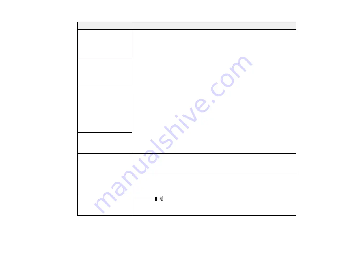
LCD screen message
Solution
Chip unit error
Chip unit not
recognized.
Replace chip unit.
Remove and reinstall the chip unit. If the error recurs, replace the chip unit
with a new one. Make sure the chip unit is installed properly on the correct
ink tank color.
Condensation may have formed inside the ink tank. Make sure the ink is at
room temperature for at least four hours.
If you still have problems, contact Epson for support.
Chip unit error
Cannot be recognized.
Remove or replace chip
unit.
Chip unit error
Chip unit not
recognized. Did you
check the names of the
supported products on
the ink pack before
adding the ink into the
printer?
Chip unit error
Replace with chip unit
that supports this printer.
Please check ink level.
Check the remaining ink in the ink tank using the scale on the ink pack and, if
necessary, refill the ink and replace the chip unit.
Make sure you have a replacement ink pack in the correct color handy.
Printing will pause if chip
unit is not replaced.
Warming Up...
OK Force to start
printing
The after heater is still warming to the specified temperature. Press the
OK
button to start printing without waiting for the after heater to warm up.
Clogged nozzles
detected.
Cleaning recommended.
Press the
pause/cancel button and select
Job Cancel
to cancel printing.
Perform a head cleaning based on the printout results.
Summary of Contents for SureColor F9370
Page 1: ...Epson SureColor F9370 User s Guide ...
Page 2: ......
Page 30: ...30 11 Firmly push the right roll core holder into the roll core ...
Page 55: ...55 3 Align the right roll core holder with the right edge of the media ...
Page 94: ...94 1 Open the ink inlet cover for the High Density Black ink shown here ...
Page 95: ...95 2 Grasp the loop at the top of the ink inlet cap and slowly remove the ink inlet cap ...
Page 104: ...104 8 Open the ink inlet cover ...
Page 107: ...107 Rest the stirring stick on the tab at the edge of the tank as shown ...
Page 108: ...108 10 Cut or tear off the ink pack spout seal ...
Page 127: ...127 1 Raise the stopper on the waste ink bottle ...
Page 128: ...128 2 Lift up the waste ink bottle and remove it from the holder as shown ...
Page 133: ...133 8 Lift up the tab on the flushing pad and remove the pad ...
Page 137: ...137 5 Align the white line on a new media edge guide with the edge of the platen ...
Page 146: ...146 Maintenance Supplies Maintenance Menu Settings ...
Page 170: ...170 14 Rotate the left roll core handle until part A is fully inserted as shown ...
Page 179: ...179 28 Remove the roll core 29 Remove the adjustment tool from the roll core ...


