11 16-BiT TiMeRS (T16)
11-4
Seiko epson Corporation
S1C17624/604/622/602/621 TeChniCal Manual
Internal count clock
PRUN
External input signal
Counter (CKACTV = 0)
n-1 n-2 n-3
0x2 0x1 0x0
n
n
Internal count clock
PRUN
External input signal
Counter (CKACTV = 1)
Underflow interrupt
0xff 0xfe 0xfd
n+3 n+2 n+1
n
0x0
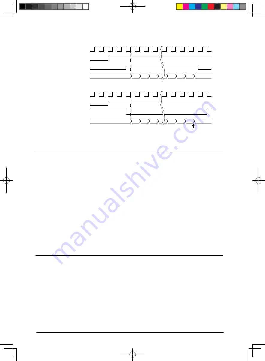
Example 1) When measuring a pulse width
Example 2) When detecting a pulse that exceeds the specified width
3.3.1 Count Operation in Pulse Width Measurement Mode
Figure 11.
Count Mode
11.4
The T16 module features two count modes: repeat mode and one-shot mode. These modes are selected using
TRMD/T16_CTL
x
register.
Repeat mode (TRMD = 0, default)
Setting TRMD to 0 sets T16 to repeat mode.
In this mode, once the count starts, the timer continues running until stopped by the application program. When
the counter underflows, the timer presets the reload data register value into the counter and continues the count.
Thus, the timer periodically outputs an underflow pulse. T16 should be set to this mode to generate periodic in-
terrupts or A/D conversion triggers at desired intervals or to generate a serial transfer clock.
One-shot mode (TRMD = 1)
Setting TRMD to 1 sets T16 to one-shot mode.
In this mode, the timer stops automatically as soon as the counter underflows. This means only one interrupt
can be generated after the timer starts. Note that the timer presets the reload data register value to the counter,
then stops after an underflow has occurred. T16 should be set to this mode to set a specific wait time or for
pulse width measurement.
Reload Data Register and underflow Cycle
11.5
The reload data register T16_TR
x
is used to set the initial value for the down counter.
The initial counter value set in the reload data register is preset to the down counter if the timer is reset or the coun-
ter underflows. If the timer is started after resetting, it counts down from the reload value (initial value). This means
that the reload value and the input clock frequency determine the time elapsed from the point at which the timer
starts until the underflow occurs (or between underflows). The time determined is used to obtain the specified wait
time, the intervals between periodic interrupts or A/D conversion triggers, and the programmable serial interface
transfer clock.


