


adjustment program menu>
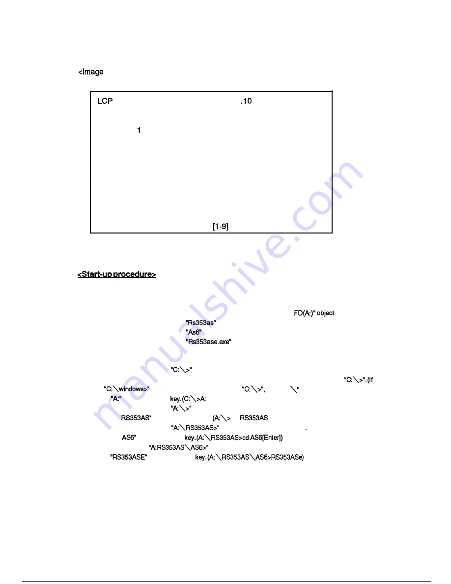
After the start-up operation, following display appear on the monitor screen.
Image Adjustment RS-353 Verl
SEIKO EPSON
0 Initialization
Flicker Adjustment
2 Ghost Adjustment
3 Sub Contrast Adjustment
4 Gamma Revise
5 Data Transfer
6 ROM Initialization
9 END
Select the number
Figure 5-l 8
1 Windows95 system
(1) Insert the floppy disk containing the image adjusting program into the FDD.
(2) Select the “My computer” from the initial display on the screen.
(3) Make sure the screen display of my computer,then select the “3.5 inch
(4) Make sure the screen display of
object, then select it.
(5) Make sure the screen display of
object, then select it.
(6) Make sure the screen display of
then select it.
2
MS-DOS or Windows3.1 system
(1) Make sure that the prompt
appears on the monitor screen. If Windows 3.1 is running, select
the MS-DOS prompt from the program manager or exit Windows and display the prompt
the
appear on the screen instead of
type “cd
then press enter key.)
(2) Type
then press enter
[Enter])
(3) Make sure that the prompt
appear on the monitor screen.
(4) Type “cd
then press enter key.
cd
[Enter])
(5) Make sure that the prompt
appear on the monitor screen
(6) Type “cd
then press enter
(7) Make sure that the
appear on the monitor screen.
(8) Type
then press enter
Summary of Contents for RS-353
Page 1: ...EPSON LCD PROJECTOR Multimedia Projector RS 353 EPSON ...
Page 8: ...Appendix Al A3 Al9 Exploded diagram Circuit diagram Chromatcity diagram ...
Page 9: ...Chapter 1 Product general ...
Page 14: ...12 3 OUTSIDE VIEW OF REMOTE CONTROLLER R e m o t e c o n t r o l l e r LED EPSON Figure 9 ...
Page 15: ...12 4 INSIDE VIEW OF REMOTE CONTROLLER Figure 10 Figure 11 l 6 ...
Page 19: ...1 4 MAIN COMPORNENT Main board Driver board Figure 19 Interface unit Figure 21 l 1 0 ...
Page 20: ...Power supply Figure 22 Light Guide block Figure 23 Optical Head unit Figure 24 l l 1 ...
Page 21: ...Projection lens unit Figure 25 Lamp inner housing Figure 26 Operation panel Figure I 27 1 12 ...
Page 22: ...1 5 SPECIFICATIONS ...
Page 30: ...Chapter 2 Theory of Operation ...
Page 37: ... 1 Main board circuit block Connect to the with cable N505 Fuse 502 POWER ON I Figure 9 2 7 ...
Page 50: ...Chapter Disassembly and assembly ...
Page 79: ...Chapter Troubleshooting ...
Page 84: ...the I s Y E S O K trough OK NO Replace main board driver work with video menu Figure 4 4 5 ...
Page 87: ...START Picture quality OK wireless RC work Figure 7 Functionary J ...
Page 88: ...Chapter Adjustments ...
Page 107: ...Appendix ...
Page 112: ......
Page 113: ......
Page 114: ......
Page 115: ... ...
Page 116: ......
Page 117: ......
Page 118: ...1 I n ...
Page 119: ...n ...
Page 120: ......
Page 121: ......
Page 122: ......
Page 123: ......
Page 124: ......
Page 125: ......
Page 126: ......
Page 127: ......
Page 128: ......
Page 129: ......
Page 130: ...A 1 2 REV A ...


