LQ-670 Service Manual
Rev. A
2-3
2.1.2 Carriage Mechanism
Carriage Mechanism consists of the carriage movement mechanism and platen gap adjustment
mechanism.
Carriage Movement Mechanism
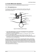
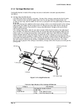
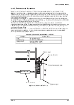
The figure below shows carriage mechanism. The top of the carriage is supported by the CR guide
frame, and down side is by the CR guide shaft. Since the carriage motor is stepping motor, the
carriage moves freely, and the rotation of the motor is conveyed to the timing belt pulley and drive the
timing belt.
A part of the timing belt is attached to the head carriage, which is moved right and left on the carriage
guide shaft by the rotation of the carriage motor. The timing belt is pre-pressed by the spring and
adjust the elastic motion of the belt which is caused by temperature changes, and keep a certain
belt strength and tension.
The carriage home position detector uses photo coupler method and is located on the right edge of
the mechanism. The detector is detected when the carriage flag interrupts the light emitted from the
photo coupler. The carriage home position control performs open loop control after the HP detector
detects standard position. After the location is determined for the carriage to move by the printing
data, the control circuit calculates the pulse of the motor phase corresponding to the distance to move,
and outputs that information to the motor. Therefore, the detection of mis-location is detected when
the home signal is detected during printing or initialization and the printer goes to the error state.
Also, the moving speed of the carriage is controlled by carriage motor drive frequency according to the
printing data.
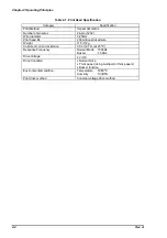
Category
Specification
Method
Photoelectric transfer method
Voltage
5VDC
±
5%
Switch Mode
Open
: In the detector range
Close : Out of the detector range
CR Motor
Timing Belt
Carriage
CR Guide Shaft
Spring
Flag
CR Guide Frame
CR Home Position
Detector
Figure 2-2. Carriage Mechanism
Table 2-2. Specification of the Carriage HP Detector
Summary of Contents for LQ 670 - B/W Dot-matrix Printer
Page 1: ...EPSON IMPACT DOT MATRIX PRINTER EPSON LQ 670 SERVICE MANUAL SEIKO EPSON CORPORATION 4007875 ...
Page 5: ...v REVISION SHEET Revision Issued Data Contents Rev A May 28 1997 First issue ...
Page 114: ...Chapter 6 Maintenance 6 1 Preventive Maintenance 6 1 ...
Page 116: ...LQ 670 Service Manual Rev A 6 2 Figure 6 1 Lubrication Points ...
Page 122: ...LQ 670 Service Manual Rev A A 5 A 2 Circuit Diagram Figure A 2 C214Main Board Circuit Diagram ...
Page 123: ...Appendix Rev A A 6 Heat Sink Q1 D51 Figure A 3 C214PSB Board Circuit Diagram ...
Page 124: ...LQ 670 Service Manual Rev A A 7 Heat Sink Q1 D51 Figure A 4 C214PSE Board Circuit Diagram ...
Page 125: ...Appendix Rev A A 8 A 3 Component Layout Figure A 5 C214 Main Board Component Layout ...
Page 127: ...Appendix Rev A A 10 A 4 Exploded Diagram Figure A 8 Exploded Diagram ...
Page 128: ...LQ 670 Service Manual Rev A A 11 Figure A 9 Exploded Diagram ...
Page 129: ...Appendix Rev A A 12 Figure A 10 Exploded Diagram ...
Page 135: ...EPSON SEIKO EPSON CORPORATION ...


