LQ-670 Service Manual
Rev. A
4-4
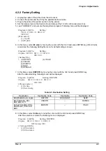
9. In this menu, Select 106 column by moving the cursor with the
↑
or
↓
and press ENTER key.
After the selection is made, the following menu is displayed.
3URJUDP/4D
6HWWLQJ'()67'
SLQV95 95 95
✼✼
,QOLQH
✼✼
>0DLQ0(18@
%L'$GMXVW
(QYHORSH
!))SDSHU
68%0(18
$+RUL]RQWDO
3&XWVKHHW
$3&XWVKHHW
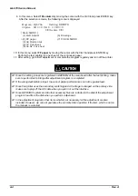
10. In this menu, select FF paper by moving the cursor with the
↑
or
↓
and press ENTER key.
Perform the test printing for one sheet of the continuous paper.
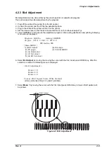
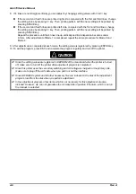
11. After setting, go to Bi-D adjustment or complete the program regularly and turn off the printer.
;
Since the setting values are registered in EEPROM of the main board after the test printing, make
sure to perform test printing after adjustment program is completed.
;
If the wrong destination is input, the correct printer performance can not be guaranteed.
;
Since this printer uses the secondary switching and AC voltage is charged on the primary side,
make sure to plug off the AC cable when you pull in or out the interface.
;
Since GWBASIC system and all other necessary files are included in the disk of the adjustment
program, load from the disk when you perform adjustment.
;
In the adjustment program, other items which is not necessary for this adjustment are also
included. However, we can not guarantee the normal printer operation if the item, which is not on
the manual, is selected.
CAUTION
Summary of Contents for LQ 670 - B/W Dot-matrix Printer
Page 1: ...EPSON IMPACT DOT MATRIX PRINTER EPSON LQ 670 SERVICE MANUAL SEIKO EPSON CORPORATION 4007875 ...
Page 5: ...v REVISION SHEET Revision Issued Data Contents Rev A May 28 1997 First issue ...
Page 114: ...Chapter 6 Maintenance 6 1 Preventive Maintenance 6 1 ...
Page 116: ...LQ 670 Service Manual Rev A 6 2 Figure 6 1 Lubrication Points ...
Page 122: ...LQ 670 Service Manual Rev A A 5 A 2 Circuit Diagram Figure A 2 C214Main Board Circuit Diagram ...
Page 123: ...Appendix Rev A A 6 Heat Sink Q1 D51 Figure A 3 C214PSB Board Circuit Diagram ...
Page 124: ...LQ 670 Service Manual Rev A A 7 Heat Sink Q1 D51 Figure A 4 C214PSE Board Circuit Diagram ...
Page 125: ...Appendix Rev A A 8 A 3 Component Layout Figure A 5 C214 Main Board Component Layout ...
Page 127: ...Appendix Rev A A 10 A 4 Exploded Diagram Figure A 8 Exploded Diagram ...
Page 128: ...LQ 670 Service Manual Rev A A 11 Figure A 9 Exploded Diagram ...
Page 129: ...Appendix Rev A A 12 Figure A 10 Exploded Diagram ...
Page 135: ...EPSON SEIKO EPSON CORPORATION ...


