LQ-670 Service Manual
Rev. A
5-18
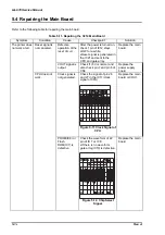
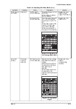
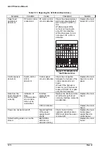
Symptom
Condition
Cause
Checkpoint
Solution
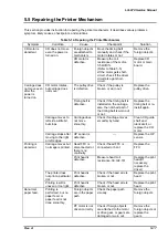
Paper feed is
abnormal.
Printing is
performed, but no
paper feed, or
paper feed is not
done smoothly.
PF motor is
defective.
Measures coil resistance
of PF motor. 16
Ω±
10%
(Refer to the Table 5-5)
•
If the coil is short
circuit, check the driver
too .
Replace the PF motor
(If necessary, replace
the driver)
Ribbon feed is
abnormal.
The ribbon is not
fed.
The ribbon
cartridge is
defective.
Remove the ribbon
cartridge. Then rotate
the ribbon feed roller
manually to check if the
ribbon is fed normally.
Replace the ribbon
cartridge.
Ribbon is caught
or stuck by the
ribbon mask.
Check if the ribbon is
fed normally by self-test.
Replace the Ribbon
mask.
Ribbon feed
mechanism of
the carriage unit
is defective.
Check if foreign objects
are caught in the ribbon
feed mechanism, or
parts are worn out.
Replace the parts of
the printer mechanism
or carriage unit.
Printing result is
dirty.
Ink spots or dirt
are seen around
the printing area.
Hole of the
ribbon mask is
defective.
Check if the ribbon
mask is broken.
Replace the ribbon
mask.
Platen gap
adjustment is not
done correctly.
Check the platen gap.
Perform the platen gap
adjustment.
(Refer to Chapter4)
False printing
Printing is
performed even if
there is no paper.
PE sensor is
defective.
Check PE detector.
(Refer to the Table 5-7)
Replace the PE
sensor.
PW(TOP)
detector is
defective.
---
Replace the PW(TOP)
detector.
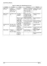
Table 5-15. Repairing the Printer Mechanism (Con.)
Summary of Contents for LQ 670 - B/W Dot-matrix Printer
Page 1: ...EPSON IMPACT DOT MATRIX PRINTER EPSON LQ 670 SERVICE MANUAL SEIKO EPSON CORPORATION 4007875 ...
Page 5: ...v REVISION SHEET Revision Issued Data Contents Rev A May 28 1997 First issue ...
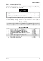
Page 114: ...Chapter 6 Maintenance 6 1 Preventive Maintenance 6 1 ...
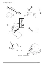
Page 116: ...LQ 670 Service Manual Rev A 6 2 Figure 6 1 Lubrication Points ...
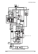
Page 122: ...LQ 670 Service Manual Rev A A 5 A 2 Circuit Diagram Figure A 2 C214Main Board Circuit Diagram ...
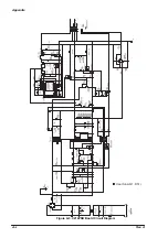
Page 123: ...Appendix Rev A A 6 Heat Sink Q1 D51 Figure A 3 C214PSB Board Circuit Diagram ...
Page 124: ...LQ 670 Service Manual Rev A A 7 Heat Sink Q1 D51 Figure A 4 C214PSE Board Circuit Diagram ...
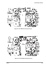
Page 125: ...Appendix Rev A A 8 A 3 Component Layout Figure A 5 C214 Main Board Component Layout ...
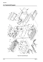
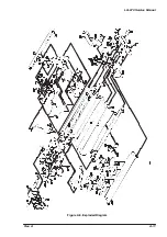
Page 127: ...Appendix Rev A A 10 A 4 Exploded Diagram Figure A 8 Exploded Diagram ...
Page 128: ...LQ 670 Service Manual Rev A A 11 Figure A 9 Exploded Diagram ...
Page 129: ...Appendix Rev A A 12 Figure A 10 Exploded Diagram ...
Page 135: ...EPSON SEIKO EPSON CORPORATION ...

