LQ-670 Service Manual
Rev. A
4-2
4.2 Adjusting and Resetting the Printer
4.2.1 Platen Gap Adjustment
This adjustment consists of platen parallelism adjustment and platen gap adjustment. Parallelism
adjustment is to adjust parallelism of track(CR guide shaft) that platen roller and print head moved.
Since the core of parallelism adjustment bushing is tilted to the CR guide shaft, it is possible to move the
CR guide shaft closer to or away from the platen roller by rotating the bushing. Parallelism adjustment is
performed by equalizing the gap between the platen roller and CR guide shaft in the right and left edges of
the printable area.
On the other hand, the platen gap adjustment is to set the gap between the platen roller side and print
head at the specified value. Since the core of the CR guide shaft is also tilted, it is possible to move the
print head closer to or away from the platen roller by rotating the shaft.
1. Remove the upper housing.
(Refer to section 3.2.4)
2. Remove the paper eject unit.
(Refer to section 3.2.5)
3. Remove the print head.
(Refer to section 3.2.2)
4. Remove the ribbon mask.
(Refer to section 3.2.3)
5. Install the print head.
6. Set the adjust lever to the “0” column position.
7. Loosen a little bit the hexagon nut securing the PG adjust lever and CR guide shaft.
8. Rotate the CR guide shaft so that the big hole of the countersinking located on the right edge of the CR
guide comes towards you.
9. Move the carriage unit to the left edge.
10. Set the thickness gauge to 0.43mm and insert it vertically between the print head and platen roller.
11. Insert the screwdriver into the hole of the countersinking located on the right edge of the CR guide
shaft and rotate the screwdriver until the platen roller and print head touches each other lightly.
12. Move the carriage unit to the right edge.
13. Insert the thickness gauge between the print head and platen roller.
14. Continue performing adjustment steps 8 to 12 rotating the parallelism adjustment bushing until the
parallelism gap of right and left becomes under 0.02mm.
15. When the parallelism gap of right and left becomes less than 0.02mm, move the carriage unit to the
center position of the printable area.
16. Insert the thickness gauge between the print head and platen roller, and rotate the CR guide shaft so
that the platen gap becomes 0.435
±
0.015mm.
17. After the adjustment is over, tighten the hexagon nut securing the adjust lever.
18. Install the ribbon mask.
;
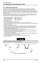
Do not rotate the platen roller during this adjustment.
CAUTION
`
Frame Assembly, Left
Frame Assembly, Right
A
B
Hole of Contersinking Parallelism Adjustment Bushing
A
B < 0.02
Figure 4-1. Platen Gap Adjustment
Summary of Contents for LQ 670 - B/W Dot-matrix Printer
Page 1: ...EPSON IMPACT DOT MATRIX PRINTER EPSON LQ 670 SERVICE MANUAL SEIKO EPSON CORPORATION 4007875 ...
Page 5: ...v REVISION SHEET Revision Issued Data Contents Rev A May 28 1997 First issue ...
Page 114: ...Chapter 6 Maintenance 6 1 Preventive Maintenance 6 1 ...
Page 116: ...LQ 670 Service Manual Rev A 6 2 Figure 6 1 Lubrication Points ...
Page 122: ...LQ 670 Service Manual Rev A A 5 A 2 Circuit Diagram Figure A 2 C214Main Board Circuit Diagram ...
Page 123: ...Appendix Rev A A 6 Heat Sink Q1 D51 Figure A 3 C214PSB Board Circuit Diagram ...
Page 124: ...LQ 670 Service Manual Rev A A 7 Heat Sink Q1 D51 Figure A 4 C214PSE Board Circuit Diagram ...
Page 125: ...Appendix Rev A A 8 A 3 Component Layout Figure A 5 C214 Main Board Component Layout ...
Page 127: ...Appendix Rev A A 10 A 4 Exploded Diagram Figure A 8 Exploded Diagram ...
Page 128: ...LQ 670 Service Manual Rev A A 11 Figure A 9 Exploded Diagram ...
Page 129: ...Appendix Rev A A 12 Figure A 10 Exploded Diagram ...
Page 135: ...EPSON SEIKO EPSON CORPORATION ...


