background image

4.

5.

Plug the monitor’s power cable first into the power inlet on the monitor

and then into an electrical outlet.

Note: If a monochrome monitor has the proper type of plug, you can

plug it into the auxiliary outlet on the back of the Equity II+

main unit.

Set the monitor switch on the front panel of the main unit for the type of
monitor you are using. (See Figure 1-2.) Slide the switch to the left for a
monochrome monitor or to the right for a color monitor.

6

Connecting the Keyboard

Follow these steps to connect the keyboard:

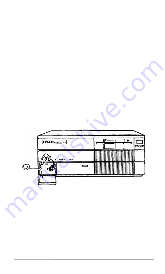
1. Open the cover on the lower left corner on the front panel of the main

unit. Press in to release the cover; then gently pull down the cover.

2. Plug the other end of the cable into the keyboard socket, as shown in Figure

1-6. Do not force the connector, but be sure to insert it all the way

Figure 1-6. Plugging the keyboard cable into the 

main 

unit

User’s Guide

1-9

Summary of Contents for EQUITY II+

Page 1: ...E Q U I T Y I I User s Guide EPSON ...

Page 2: ...EPSON Equity II User s Guide Y 1 6 2 9 9 1 1 0 3 0 0 ...

Page 3: ...on No patent liability is assumed with respect to the use of information contained herein While every precaution has been taken in the preparation of this publication Seiko Epson Corporation assumes no responsibility for errors or omis sions Nor is any liability assumed for damages resulting from the use of the information contained herein Further this publication and features described herein are...

Page 4: ...l suggestions The user may find the following booklet prepared by the Federal Communications Commission helpful Television Interference Handbook This booklet is available from the U S Government Printing Office Washington DC 20402 Stock No 004 000 00450 7 Note If the interference stops it was probably caused by the computer or its periph eral devices To further isolate the problem Disconnect the p...

Page 5: ...iv User s Guide ...

Page 6: ...play 2 Using the Equity II Inserting and Removing Diskettes Special Keys on the Equity II Keyboard Selecting Execution Speed Resetting the Computer Turning Off the Computer 3 Using Disks and Disk Drives How Disks Work Choosing Diskette Drives for the Equity II Drive and diskette incompatibilities Caring for your Disks and Disk Drives Protecting your Data Making backup copies Write protecting diske...

Page 7: ... Hard Disk Problems 5 3 Software Problems 5 3 Printer Problems 5 4 Option Card Problems 5 4 Appendixes A Jumper Settings Changing a Jumper Setting Memory Card Jumpers Main Circuit Board Jumpers Multi function Card Jumpers B Equity II Specifications CPU and Memory Controllers Interfaces Power Supply Mass Storage Keyboard Environmental Requirements Physical Characteristics CPU Only Power Requirement...

Page 8: ...ite protect notch Write protect switch Back and side panel screws Sliding back the cover Removing the cover Optionslots 16 bit and bit option cards Removing an option slot cover Inserting an option card Location of cards A 2 Jumper positions A 3 Removing memory card retaining screw A 4 Memory card jumpers A 5 Main circuit board jumpers A 6 Disconnecting drive drive cable from multi function card A...

Page 9: ...kette compatibility 3 2 3 2 3 inch drive diskette compatibility 3 3 A 1 Memory card jumper settings A 3 A 2 Main circuit board jumper settings A 5 A 3 Multi function card jumper settings for parallel port A 6 A 4 Multi function card jumper settings for serial port A 7 v i i i User s Guide ...

Page 10: ...ial interface and a parallel inter face These interfaces let you connect an Epson printer or plotter or almost any peripheral device you choose You can further expand the capabilities of your Equity II by adding optional cards to which you connect external devices The Equity II has six option slots in which you can install option cards One slot holds the paral lel and serial interfaces You choose ...

Page 11: ...e software Additionally the Equity II supports multiple users and multiple task ing with the appropriate operating system Consult your Epson dealer for more information How to Use this Manual This user s guide explains how to set up and care for your Equity II It also describes how to start using your system and install optional devices You may not need to read everything in this book some section...

Page 12: ... this manual describes the diagnostics programs for your Equity II You run these diagnostics programs the first time you set up your system and any time you change the configuration of your Equity II User s Guide Intro 3 ...

Page 13: ...tes both of which provide the MS DOS commands used for daily operation Operating diskette 1 contains the individual commands Operating diskette 2 contains menus you can use to access many of the same commands This diskette also provides the MS DOS Help utility and the GW BASIC programming language l A reference diskette that contains a special group of programs called diagnostics You use these pro...

Page 14: ...et up your new system choose an appropriate place Whether you use your computer at home or in the office you need to find a comfortable convenient location where it can run properly Choose a location that provides the following A large sturdy desk or table Make sure it can easily support the weight of your system including all its components A flat hard surface Soft surfaces like beds and carpeted...

Page 15: ...on the rear panel of the Equity II reduces the number of wall outlets you need l No electromagnetic interference Locate your system away from any electrical device that generates an electromagnetic field Even a tele phone can cause trouble especially if you keep diskettes right next to it 3 Arranging the Components First decide how you want to arrange the different parts of your system Figure 1 1 ...

Page 16: ...ver and you can gently pull it down to view the switches Floppy disk drive Disk lock Floppy disk drive slots Figure 1 2 Front panel l POWER switch Use this switch to turn the Equity II on or off l Floppy disk drive The top drive is a floppy disk drive that uses high density 1 2MB diskettes l Disk lock release latch To lock a diskette in place turn this latch down until it is vertical To release a ...

Page 17: ...button to reset the computer When an operat ing system is running and the computer is unlocked you can press the RESET button to reboot the system CPU SPEED switch Use this switch to select the CPU s execution speed slide it to the left to run at 8 MHz and slide it to the right to run at 12 MHz MONITOR SELECT switch Slide this switch to the left if you are using a monochrome monitor or to the righ...

Page 18: ...ial port Allows you to connect a peripheral with a serial interface such as a modem another computer or a printer Option card access slots The Equity II has six slots to hold up to six option cards Option cards allow your computer to control your peripherals or enhance your computer s performance One option card slot holds the parallel and serial interfaces as well as the floppy disk controller If...

Page 19: ...ur monitor See Chapter 4 for instructions on how to remove the main unit s cover and install an option card 1 Place your monitor on top of or near the Equity II main unit It is easiest to connect the monitor cable if the backs of the monitor and main unit face you 2 If necessary connect the monitor cable to the monitor Some monitors come with permanently attached cables 3 Connect the appropriate e...

Page 20: ...o monitors Consult Table l l to make sure your card and monitor match Table 1 1 Monitor video card compatibility Monitor Video card output type Monochrome Monochrome or 9 pin output enhanced graphics TTL compatible Color or enhanced Color graphics or 9 pin RGB output color enhanced graphics Composite color Color graphics RCA type jack or monochrome Note Be sure to set the switches on the video car...

Page 21: ... using See Figure 1 2 Slide the switch to the left for a monochrome monitor or to the right for a color monitor 6 Connecting the Keyboard Follow these steps to connect the keyboard 1 Open the cover on the lower left corner on the front panel of the main unit Press in to release the cover then gently pull down the cover 2 Plug the other end of the cable into the keyboard socket as shown in Figure 1...

Page 22: ...gs on the bot tom To adjust the legs turn the keyboard over and lift each leg upward until it locks into place as shown in Figure 1 7 You can adjust the legs to two different positions or leave them flat Figure 1 7 Adjusting the keyboard legs 1 10 User s Guide ...

Page 23: ...main unit you need an IBM compatible printer cable If you are not sure which one you need consult your Epson dealer Once you have a printer cable follow these steps to connect your printer to the parallel interface on the main unit 1 Place the printer next to your system 2 Before you connect the printer be sure the power switches on both the main unit and the monitor are off 3 Connect the appropri...

Page 24: ...serial RS 232C port at the back of the main unit The Equity II uses a DB 9P connector so be sure you have an AT compatible cable or an adapting cable that converts the 9 pin output to the standard 25 pin output To connect a serial device follow the same steps above for connecting a parallel device You need to ensure the serial port is set up so it functions properly If you are using the port for a...

Page 25: ...r or injuring yourself Never turn the computer on or off with a protector sheet in the disk drive Do not attempt to dismantle any part of the computer Only remove the top cover to install and remove option cards If there is a hardware problem you cannot solve after reading Chapter 5 on troubleshooting or if you want to install an optional 80287 math coprocessor consult your Epson dealer Always tur...

Page 26: ... the computer press in the power switch on the front panel of the main unit as shown in Figure 1 10 The power indicator on the front panel lights up and the cooling fan inside the main unit starts After a few seconds the computer begins to perform an internal self test Figure 1 10 Turning on the power If you cannot see the screen display clearly use the controls on your monitor to adjust the brigh...

Page 27: ...system insert the system diskette you want to use see Inserting and Removing Diskettes in Chapter 2 Refer to your MS DOS or other operating system manual for details on how to use the system Note Use only a backup copy of the system diskette for daily use and keep the original in a safe place See your MS DOS manual to find out how to make a backup copy If your system has a hard disk you need to pr...

Page 28: ...1 16 User s Guide ...

Page 29: ...ith the label face up and the write protect notch to the left so that the read write slot is away from you Then slide it into the disk drive as shown in Figure 2 1 When the diskette is all the way in turn the latch down until it locks into the vertical position This keeps the diskette in place and enables the read write heads in the disk drive to access the diskette Figure 2 1 Inserting a diskette...

Page 30: ...ress the disk drive button to lock it in place To remove the diskette press the button to release it and pull it out of the drive WARNING Never remove a diskette or turn off the computer while the drive indicator light is on You could lose data Also be sure to remove all diskettes before you turn off the computer Special Keys on the Equity II Keyboard Certain keys on your keyboard serve special fu...

Page 31: ...ates current operation The Num Lock Caps Lock and Scroll Lock keys work as toggles when you press them When the function is enabled the corresponding light on the upper right corner of the keyboard is on when the function is dis abled the light is off Selecting Execution Speed The Equity II can operate at two different execution speeds 8 MHz or 12 MHz At the faster speed the computer performs all ...

Page 32: ...mands you can reset the computer and try the same operation again However resetting erases all data in the computer s temporary memory RAM so reset your computer only as a last resort In MS DOS you can hold down Ctrl and press C to stop a program s operation and return to the MS DOS command prompt If an error occurs try this method before you reset the computer WARNING Do not reset the computer to...

Page 33: ...panel This method works even when the keyboard does not respond to your commands If this does not correct the problem try the third method Remove any diskettes from the floppy disk drives Turn off the monitor and any peripheral devices and then turn off the Equity II using the power switch on the front panel of the main unit Wait five seconds and then switch the power back on Turning Off the Compu...

Page 34: ...User s Guide ...

Page 35: ...rotective jackets Like a record a diskette has circular tracks on both sides The computer stores the data you enter as magnetic patterns on these circular tracks A small read write head in the disk drive interprets the magnetic pat terns When a diskette is in a drive the read write head is right over the large oval hole in the diskette jacket This hole allows the read write head to access the disk...

Page 36: ...ed high density 1 44MB disk ettes These diskettes contain 80 tracks per side 18 sectors per track and hold up to 1 44MB of information If your computer has more than one of these drive types you need to be aware of certain incompatibilities between the drives and the diskettes they use These incompatibilities also apply to the same type of diskette drives on other compatible computers Drive and di...

Page 37: ...our MS DOS manual for instructions You can copy files between a hard disk and any type of diskette See your MS DOS or other software manual for instructions on how to copy files Caring for your Disks and Disk Drives To avoid damaging floppy and hard disks you need to care for them properly Take these precautions to avoid losing data Keep disks away from dust and dirt Small particles of dust or dir...

Page 38: ...ette Use only soft tip pens not ballpoint pens or pencils to write on a label that is already on a diskette Do not remove a diskette or turn off the computer while the drive light is on This light indicates that the computer is copying data to or from a disk If you interrupt this process you can destroy data Remove all diskettes before you turn off the computer If you have a hard disk drive take t...

Page 39: ... store them away from your originals Your MS DOS manual describes how to make a backup copy of your MS DOS startup and operating diskettes To make backups of other MS DOS diskettes use the DISKCOPY command or the DU Disk Utility program If you have a hard disk keep backup copies of all your program files on floppy disks and regularly copy important data files to floppy disks as well For more infor...

Page 40: ...rner on the back shown in Figure 3 2 To write protect this diskette slide the switch down toward the edge of the diskette so there is a hole where the switch used to be To write to a 3 inch diskette move the switch up toward the center of the diskette so the hole is covered Figure 3 2 Write protect switch Write protected I 3 6 User s Guide ...

Page 41: ...iskette you place in the drive When copying is complete you see a prompt to insert the original diskette Because you may swap diskettes this way often it is easy to forget which diskette is which One way to avoid accidentally losing data is to hold the diskette for one drive in your left hand and the diskette for the other in your right You can also write protect your source diskette For more info...

Page 42: ... Disk program to format the hard disk Partition the hard disk to run the MS DOS operating system using the MS DOS program FDISK Format the MS DOS partition with the MS DOS program SELECT Copy the MS DOS utility programs to the hard disk using SELECT For instructions on running the diagnostics program see the Diagnos tics section of this manual For instructions on how to use the MS DOS programs ref...

Page 43: ...t your dealer for more informa tion This chapter describes how to remove and replace the main unit s cover and install and remove an option card Removing the Cover To install an option card you need to remove the cover from your Equity II WARNING Never open the cover of the Equity II while it is plugged into an electrical outlet Before you open the cover turn off the power switches on the main uni...

Page 44: ...faces you Hold on to the two sides of the cover and carefully pull it straight toward you away from the back of the computer as shown in Figure 4 2 The cover fits tightly so if you have trouble moving it at first keep pulling it firmly Figure 4 2 Sliding back the cover 4 2 User s Guide ...

Page 45: ... off Set the cover aside Installing an Option Card Figure 4 4 shows the six option slots in the Equity II Slot 6 contains the parallel and serial interface and floppy disk controller card Be sure to install the video card in slot 5 Slots 1 5 and 6 are designed for 8 bit option cards and the other three slots 2 through 4 are designed for 16 bit option cards Figure 4 5 shows both types of cards As y...

Page 46: ...Figure 4 4 Option slots 16 bit option car Figure 4 5 16 bit and bit option cards 4 4 User s Guide ...

Page 47: ...u have such a card the instructions that come with it specify which slot you need to use Option cards fit in the slots only one way but be sure to examine the card first and follow the instructions closely 1 Decide which option slot you want to use If the card has an external connector such as a monitor card you need to remove the option slot cover at the back of that slot See Figure 4 6 Remove th...

Page 48: ...especially the gold edged connections If you need to set it down before you install it place it on top of its original packing material with the component side facing down Keep the card s packing materials in case you remove the card later 3 Grip the card firmly by the top corners and position it at the top of the slot Make sure the contact pins point down and the components face the inside of the...

Page 49: ...on setup see below be sure to change it back Replacing the Cover After you install or remove an option card follow these steps to replace the main unit s cover I 2 3 4 5 6 With the front of the computer facing you position the cover on the computer Pull the sides outward slightly and lower the cover over the computer Guide the curved edge on the bottom of the cover along the bottom of the computer...

Page 50: ... You may also need to add some commands in the configuration file on your system disk See your MS DOS manual for instructions When you finish installing an option and reconfiguring the system you should test the option if possible Some options come with their own test programs and you can test others using the diagnostics programs on the reference diskette that came with the Equity II These includ...

Page 51: ...h follow these steps to find a solution 1 Check to see if the power light on the front panel is on If it is not remove any diskettes and then turn off the power Wait five seconds then turn the power back on 2 If the power light still does not come on turn off the power switch Check to see that the power cable is securely connected to both the AC inlet on the back panel and the electrical outlet Th...

Page 52: ...g 1 Wait a few seconds Some operations take longer to perform than oth ers For example a spreadsheet program takes longer to recalculate an entire spreadsheet than to record one figure Also BASIC programs that have a lot of calculations to perform can take several minutes or even hours Be aware of the task the computer is performing and judge the time accordingly 2 If the computer remains locked u...

Page 53: ...rd Disk Drive in Chapter 3 and refer to your MS DOS manual If you cannot access data stored on your hard disk you may have acci dentally repartitioned or reformatted part or all of the hard disk If you have not done so and your hard disk does not function properly have an autho rized Epson service center check your hard disk Never open the air tight container that encloses the recording disk Softw...

Page 54: ...ption card and get unexpected results check the following 1 2 3 4 5 6 Is the option card installed correctly Did you follow the setup and operation procedures in the option card instructions Did you set any necessary DIP switches or jumpers on the option card See your option card instructions Did you change any necessary jumper settings in the main unit See Appendix A Jumper Settings If you added ...

Page 55: ...you decide to do it yourself be very careful when you follow the procedures in this appendix There are many system components that can be damaged accidentally The Equity II jumpers you may need to change are on the l Main circuit board l Memory card l Multifunction card parallel port serial port and floppy disk controller Figure A l shows where each of these cards is located in the computer Multi ...

Page 56: ...determined by where the jumper is placed either between pin A and the middle pin position A or between pin B and the middle pin position B Figure A 2 shows both positions Position A Position B be be B A A A Figure A 2 Jumper positions To move a jumper from one position to the other use needle nose pliers or tweezers to lift it off the board and gently move it to the other position Be careful not t...

Page 57: ... on the memory card Table A 1 Memory card jumper settings JumperZnumber Function 1 3 A A 640KB B A 512KB disable upper 128KB B B 256KB disable upper 384KB A Select EPROM size 27128 B Select EPROM size 27256 l Default setting To access the memory card jumpers you need to remove the card from the main unit first 1 Remove the retaining screw from the bracket on the memory card as shown in Figure A 3 ...

Page 58: ...Main Circuit Board Jumpers The jumpers on the main circuit board control the following functions l Number of wait states for EPROM If necessary you can change the number of wait states 1 or 2 used by the EPROM Selectable wait states are available only when your computer is running at 12MHz Please consult your dealer for assistance l Number of wait states for 16 bit device access If necessary you c...

Page 59: ...ettings Jumper number 1 Function 1 2 3 4 5 A 1 wait state for EPROM access l B 2 wait states for EPROM access A A 1 wait state for 16 bit option card B A 2 wait states for 16 bit option card A B 3 wait states for 16 bit option card B B 4 wait states for 16 bit option card l A A Set coprocessor clock at 8 MHz B B Set coprocessor at 1 3 of CPU speed Default setting To access the main circuit board j...

Page 60: ... want it to be the primary port you need to change the jumpers on the multi function card so the built in port becomes secondary JPT2 and COM2 Table A 3 shows the jumpers on the multi function card that con trol the parallel port Table A 3 Multi function card jumper settings for parallel port Jumper number Function 3 4 10 A A A Enable built in port as primary l B A B Enable built in port as second...

Page 61: ...ry B Disable built in port l Default setting To access the multi function card jumpers you need to remove the card from the computer 1 Unplug the disk drive cable from the card as shown in Figure A 6 Pull it straight up and out then lay it to one side Figure A 6 Disconnecting disk drive cable from multi function card 2 Remove the retaining screw from the multi function card at the back panel of th...

Page 62: ...d from the slot pull it straight up and set it on a soft surface with the components facing up Figure A 8 shows where the jumpers are located Change them needed and then reverse the three steps above to reinstall it Figure A 8 Multi function card jumpers as A 8 User s Guide ...

Page 63: ...mory card expandable to 15 5MB maximum with expansion cards 32KB expandable to 64KB selectable alternate ROM for custom use 80287 8 MHz support optional Supports up to two drives available in any of four formats double density 360KB double density 720KB high density 1 2MB or high density 1 44MB control ler on multifunction card Supports up to two drives available in multiple formats including 10MB...

Page 64: ...40 W peak 5 VDC 12 VDC 5 VDC 12 VDC 50 60 Hz Mass Storage Standard Optional Optional Optional Optional Three drives maximum configurable using three half height slots horizontal mounts 5 inch half height floppy disk drive double sided high density 1 2MB storage capacity 5 inch half height floppy disk drive double sided high density 1 2MB storage capacity 51 G inch half height floppy disk drive dou...

Page 65: ...Environmental Requirements Temperature Operating range 41 to 90 F 5 to 35 C Storage range 4 to 140 F 20 to 60 C Humidity Operating range 20 to 80 non condensing Storage range 10 to 90 non condensing Physical Characteristics CPU Only Width inches mm Depth inches mm Height inches mm Weight pounds kg 15 7 400 16 3 414 6 1 155 19 8 9 Single floppy disk drive 25 08 11 4 Single floppy disk drive and one...

Page 66: ...son or IBM compatible mono chrome monitor 80 character x 25 line display 9 x 14 character block installs in option slot High contrast screen 16 colors etched surface to reduce glare 18 MHz video bandwidth Supports Epson and IBM compatible mono chrome or color monitor monochrome text color graphics and Hercules mono chrome graphics switch selectable installs in option slot Supports Epson and IBM co...

Page 67: ...xtra copy of a program data file or disk kept in case your working copy is damaged or lost Bit A binary digit 0 or 1 The smallest unit of computer storage The value of a bit represents the presence 1 or absence 0 of an electric charge Boot To load a program or an operating system Byte A sequence or group of eight bits that represents one character Character Anything that can print in a single spac...

Page 68: ...ack of stored data and controls all input and output operations Cursor The highlighted marker that shows your position on the screen and moves as you enter and delete data Data Information stored or processed by a computer Data diskette A formatted diskette used to store files Diagnostics The tests and procedures the computer performs to check its internal circuitry and set up its configuration DI...

Page 69: ...torage capacity of 360KB or 720KB File A group of related pieces of information called records or entries stored together on disk Text files consist of words and sentences Program files consist of code and are used by computers to interpret and carry out instructions Floppy disk See Diskette Format To prepare a new disk or erase an old one so that it can receive informa tion Formatting a disk divi...

Page 70: ... electricity passes through it like the indicator lights on the front panel of the Equity II Main unit The Equity II computer Megabyte MB A unit used to measure storage space in a computer s memory or on a disk One megabyte equals 1 048 576 bytes Memory The area where your computer stores data Memory contents can be permanent and inalterable ROM or temporary RAM Microprocessor A small version of a...

Page 71: ...OS Option card A card you install inside the Equity II main unit to provide additional capabilities such as more memory a hard disk drive or a mouse Parallel The type of interface that transmits data in groups of bits See Interface Serial Partition To divide a hard disk drive into separate sections for use by different operating systems Peripheral A device such as a printer or a modem connected to...

Page 72: ...ating system Resetting clears RAM RGB Red Green Blue An RGB monitor displays in high resolution color ROM Read Only Memory A portion of memory that can only be read and cannot be used for temporary storage ROM retains its contents even when you turn off the power RS 232C A widely used standard type of serial interface You can easily connect RS 232C compatible devices to the Equity II Sector A cont...

Page 73: ... double sided double density disk ette and 80 tracks on each side of a double sided quad density or a double sided high density diskette Write To store data on a disk Write protect To prevent a diskette from being overwritten by placing a write protect tab over the notch on the side of the diskette 5 inch or setting the write protect switch 3Cnch When a diskette is write protected you cannot erase...

Page 74: ...C 8 User s Guide ...

Page 75: ...ity diskettes 3 2 3 5 3 Configuration 4 8 Connecting keyboard 1 9 power cord 1 6 printer 1 11 monitor 1 7 Connector monitor 1 7 9 option card 4 3 7 printer 1 11 13 RCA 1 8 slot 4 3 7 Contrast control monitor 1 14 5 2 Control codes Ctrl 2 3 Ctrl Alt Del 2 5 Ctri C 2 4 Controllers floppy disk 1 6 4 1 4 3 A 1 B 1 hard disk 1 6 4 1 B 1 parallel interface 1 6 1 11 4 1 4 3 A 1 serial interface 1 6 1 12 ...

Page 76: ...ensity diskettes 3 2 3 B l Double sided diskettes 3 2 3 Drive See Disk drive Drive diskette compatibility 3 2 3 DRIVER SYS command 3 3 DU 3 5 E 80287 math coprocessor Intro 2 1 13 A Enhanced graphics card Intro 1 B 4 EPROM A 3 5 Expansion memory Intro 2 4 8 External devices Intro 1 F FDISK program 3 8 Floppy disk See Diskette Floppy disk controller 1 6 4 1 4 3 A 1 B 1 Floppy disk drive See Disk dr...

Page 77: ...1 9 10 special keys 2 3 L Labeling diskettes 3 4 Latch disk drive 1 4 2 1 Loading an operating system 1 15 M Magnetic surface disks 3 1 3 4 Main circuit board location A 1 jumpers A 4 Main memory A 2 B 1 Main unit cover removing 4 1 cover replacing 4 7 front panel 1 3 4 power switch 1 4 1 14 back panel 1 5 6 Mass storage B 2 Math coprocessor Intro 2 1 13 A 5 B 1 Memory Intro 2 B 1 See also RAM Mem...

Page 78: ...et 1 6 5 1 light 1 5 1 14 2 4 5 1 requirements B 3 source 1 3 1 14 supply B 2 switch 1 14 turning off 2 5 turning on 1 14 Power cord connecting 1 6 Preparing hard disk 3 7 8 Printer cable 1 11 12 connecting 1 11 13 parallel 1 6 1 11 B 1 problems 5 4 serial 1 12 El Printing graphic characters 1 13 Protecting data 3 5 6 R RAM Random access memory Intro I 1 15 2 4 A 2 B 1 RCA connector 1 8 Read only ...

Page 79: ...le sided diskettes 3 2 Slots option 1 6 4 3 5 Software problems 5 4 Speaker interface B 2 Special character set 1 13 Specifications B 1 Speed switch 1 5 2 3 5 3 Startup diskette 1 1 Storing diskettes 3 4 Switch power 1 4 1 14 System configuration 4 8 diskette 1 1 1 15 3 5 prompt 1 15 V Video card Intro l 1 7 8 4 1 B 4 Video monitor See Monitor Voltage switch 1 6 W Write protecting diskettes 3 5 5 ...

Page 80: ...Diagnostics This section describes the diagnostics programs you use the first time you set up your system and any time you make changes to it ...

Page 81: ...Diagnostics ...

Page 82: ...tions Conditional Format Normal Unconditional Format Destructive Surface Analysis Non destructive Surface Analysis 3 Formatting a Diskette 1 1 1 1 1 2 1 4 1 5 1 6 1 7 2 1 2 1 2 2 2 5 2 6 2 8 3 1 4 Performing System Diagnostics 4 1 Using the System Diagnostics Program 4 2 Modifying the DEVICE LIST 4 3 Selecting a test 4 4 Resuming from an error 4 5 System Board Check 4 6 Memory Check 4 6 Keyboard C...

Page 83: ...quential seek check 4 18 Random seek check 4 18 Write read check 4 18 Speedcheck 4 19 Disk change check 4 19 Run all above checks 4 20 Math Coprocessor Check 80287 4 20 Parallel Port Printer Interface Check 4 21 Parallel Port on Video Adapter Check 4 21 Serial Port RS 232C Check 4 21 Alternate Serial Port Check 4 23 Dot matrix Printer Check 4 23 Hard Disk Drives and Controller Check 4 24 Seekcheck...

Page 84: ...stem Device Check C 1 Clock and CMOS RAM Check C 2 RAM Check C 2 Keyboard Controller and Keyboard Check C 3 Display Card Check C 3 Optional RAM Check C 4 Floppy Disk Drive Seek Check C 4 Hard Disk Controller and Hard Disk Check C 4 Tables A 1 Error codes and messages A 1 B 1 Drive types B 1 Diagnostics V ...

Page 85: ...Diagnostics ...

Page 86: ...this program to format a diskette for use by the System diagnostics tests This pro gram is provided for convenience only so that you can format a diskette without exit ing diagnostics System diagnostics Use these programs whenever you add or remove optional devices or if you suspect that the system is defective You also run these diagnostics after moving the system from one place to another and af...

Page 87: ...t for a few seconds 2 Place the reference diskette in drive A and close the door of the disk drive 3 Turn on the computer When you turn the power on the computer performs a self test and then automatically starts the diagnostics program The Power on Self Test Whenever you turn on or reset the computer the system performs a built in diagnostics program called the power on self test This test checks...

Page 88: ... a number from 1 to 5 and press Enter Option 3 Format diskette is included on the OPERATlON MENU for convenience only This option lets you format diskettes for use by the System diagnostics tests without exiting from the diagnostics programs To use the other utility programs on the reference diskette select 0 from the OPERATION MENU Then start the utility from the MS DOS prompt Option 0 exits the ...

Page 89: ...ostics DIAGSYS Prepare hard disk for moving HDSIT You can copy these MS DOS commands with the exception of DIAGSYS to your hard disk or to a directory on another floppy disk You can then execute them as individual MS DOS commands To copy these commands use the COPY command described in your MS DOS manual You can also execute the commands directly from the reference diskette without loading diagnos...

Page 90: ...h Setup in CMOS RAM which is backed up by a battery When you turn on the computer it searches CMOS RAM to obtain the correct installation information If there is a difference between the information in CMOS RAM and the actual configuration you see a prompt to run the Setup program Using the Setup Program To start the Setup program from the diagnostics OPERATION MENU press 1 and then press Enter To...

Page 91: ...e any changes or if you want to cancel the changes you made you can return to the OPERATION MENU or the MS DOS prompt without re booting the computer Press 1 to highlight the option Exit without saving and press Enter When the settings are correct press 1 to highlight the option EXIT AND SAVE and press Enter The program writes the settings in CMOS RAM and then resets the computer using the new con...

Page 92: ...ain or Expansion 3 When the cursor block is on the Main option this message appears at the bottom of the screen T return to main menu 1 select option Enter change main memory size Press Enter to change between the possible amounts of main memory You can set the amount of main memory to 256KB 512KB or 640KB 4 When the cursor block is on the Expansion option this message appears at the bottom of the...

Page 93: ... Enter Another menu appears to show the current setting If you have an 80 column color monitor installed you see 2 To change the monitor type press Enter This menu displays listing the various options Choose the monitor type according to the combination of monitor and video card that you are using l If you have a monochrome monitor choose Monochrome 80 regardless of the type of video card to which...

Page 94: ...hat makes use of the 80287 coprocessor The 80287 works together with the 80286 which is the main processor to process mathematical computations very quickly When you install an 80287 use this option to notify the computer so it will use the coprocessor If you remove the 80287 use this option to delete the coprocessor from the equipment list this prevents software from trying to use the 80287 comma...

Page 95: ...nter You see this menu 729 KB drive 3 5 1 2 MB drive 1 44 MB drive 3 5 3 Press 1 to move the cursor block to the appropriate drive type and press Enter to make your selection To return to the menu of drives without changing the drive type press t or ESC 4 To change a hard disk drive consult the list of drive types in Appendix B to find the correct number for the type of drive you have installed Th...

Page 96: ...ustments such as daylight saving time Your computer automatically adjusts for leap years Note that even though MS DOS and your applications programs may use a different format the real time clock uses a 24 hour time format to store the time To set the real time clock follow these steps 1 On the main menu press 1 to move the cursor block to Real time clock and press Enter The time and date appear l...

Page 97: ...sing two digits for the month and the day the program automatically inserts the dashes When the date is correct press Enter If you enter an invalid date the computer beeps and the date does not change 4 When both the time and date are correct press t to return to the main menu to change other settings 1 8 Diagnostics ...

Page 98: ...tions If you are using only MS DOS you need only one partition Refer to your MS DOS manual for details on using FDISK to create a parti tion and using SELECT to format it for this operating system You may need to reformat a hard disk if you have a serious problem with the drive However before completely reformatting the disk use the Non destructive surface analysis test to decide if formatting is ...

Page 99: ...face analysis before formatting the disk this routine finds all bad tracks that are not flagged If the analysis shows that all the tracks listed as bad are already flagged you can then use the Conditional format Normal option to format the disk If the analysis matches the list of bad tracks but they are not flagged run the Destructive surface analysis to flag the tracks before formatting the disk ...

Page 100: ...unt of good tracks nnnn The program then displays a warning about the consequences of pro ceeding with formatting WARNING ALL DATA WILL BE DESTROYED IN ALL PARTITIONS OF HARD DISK NOT JUST IN MS DOS PARTITION Do you want to start formatting Y N If there are no tracks with other errors and you are absolutely sure that you want to format the hard disk press Y and Enter The program then asks you once...

Page 101: ... unflagged error s or is unformatted Press ENTER to return to the menu Press Enter This may mean that the drive has never been formatted or that an error was not flagged If you see this message it is best to consult your dealer If you want to format the disk after receiving this error message do the following 1 2 3 If the drive is not formatted perform the Unconditional format Option 2 and enter a...

Page 102: ...g from the default value of three Only do this if the documentation with your hard disk recommends a different value You see this prompt Do you want default interleave of 3 Y N To accept the default press Y and Enter To change the value press N and Enter You see this prompt Enter interleave factor 1 16 Type the recommended value and press Enter The next screen allows you to edit the table of bad t...

Page 103: ...nder or head number a reminder of the range of values appears and the program asks you to enter the value again When you complete a valid entry it appears in the table and you can select another command If you make a mistake move the cursor block to the incorrect track and press C to alter the track data Or you can press D to remove the track from the table Change the track data just like you add ...

Page 104: ...to zero When the analysis is complete the program displays a complete report on the status of the disk including a table of unflagged tracks that produced write read errors For a hard disk with one flagged bad track a display like this appears Analysis finished Count of tracks flagged bad Count of tracks with write read errors Count of good tracks No write read error was detected No data was destr...

Page 105: ...tart the test press 4 and then Enter You see these messages Analyze Hard Disk Read Verify check for all tracks Current cylinder is xxxx As each track is checked the current cylinder is displayed The cylinder number counts down to zero as the disk is checked When the analysis is complete the program displays a summary of the status of the disk This summary lists these counts l Flagged bad tracks l ...

Page 106: ...lso to test a 360KB drive always use a double density diskette that you formatted in a 360KB drive The Format diskette program destroys any data on the diskette When formatting your diskettes the program also initializes the directory and file allocation tables When you select option 3 from the OPERATION MENU you see this message and prompt Format Diskette Insert diskette for drive A and strike EN...

Page 107: ...mat a double density diskette you see this warning message WARNING This disk is not suitable for testing a 360 KB drive Press Enter to return to the menu For a complete description of the FORMAT command refer to the MS DOS manual Diagnostics ...

Page 108: ...ystem with the reference disk ette in drive A Then select option 4 from the OPERATION MENU If you start this program in any other way some tests may produce strange results You can test these devices the program identifies each one with a spe cific reference number 1 System 2 Memory 3 Keyboard 4 Monochrome display adapter and CRT 5 Color graphics adapter and CRT 6 Floppy disk drives and controller...

Page 109: ...evices have been installed DEVICE LIST 1 System board 2 Memory 3 Keyboard 5 Color graphics adapter and CRT 6 Floppy disk drives and controller 9 Parallel port printer interface 11 Serial port RS 232C port 14 Dot matrix printer 17 Hard disk drives and controller Is the DEVICE LIST correct Y N If the list correctly describes your system press Y and then Enter If a device is missing from this list or...

Page 110: ... l Add devices 2 Delete devices 0 Exit Enter selection number To add a device to the list press 1 and then Enter The program displays a list of other devices that are not currently included in the DEVICE LIST You see a menu similar to this Additional DEVICE LIST 4 Monochrome display adapter and CRT 7 Math coprocessor 80287 12 Alternate serial port 21 Alternate parallel port 81 Parallel port on vid...

Page 111: ...mber of the item you wish to delete and press Enter You can delete as many devices as necessary When the DEVICE LIST is correct press 0 and then Enter The screen displays the modified DEVICE LIST for a final check If the list is correct press Y and Enter You are now ready to select a test Selecting a test From the DEVICE LIST select the device you wish to test Type the number of the device then pr...

Page 112: ...If an error occurs during a test the test stops at that point and an error code and error message display If you want to record the problem you can print out the message on your printer You see this prompt Do you want a printout of the error message s Y N To continue without printing the error message press N and Enter Before you request a printout be sure your printer is turned on and on line and...

Page 113: ... l The system ROM l The real time clock CMOS RAM and battery l The main integrated circuits The checks made on the 80286 CPU chip are extremely comprehensive and ensure that the CPU instruction set including protected mode operation is functioning correctly If an error occurs make a copy or a printout of the error code and message and contact your dealer or Epson for customer service Attempting to...

Page 114: ...ove 640KB which is normally not available to MS DOS is checked using the protected mode of the 80286 CPU chip Keyboard Check Use this option to check the operation and the configuration of the keyboard The program first checks the keyboard controller during this check you see the green indicator lights on the keyboard flash Before checking the operation of the keys you must select the appro priate...

Page 115: ... do not match If all the keys function correctly and match the characters displayed press Y and then Enter If all the keys function but the characters displayed do not match the keys press Y and then Enter Then re select the keyboard test from the DEVICE LIST and check that you selected the correct keyboard layout You can find diagrams of all the international keyboard layouts in the MS DOS manual...

Page 116: ...Enter The computer checks the video RAM display memory on the display adapter by writing certain data to memory then reading it back and compar ing it to the written data The computer also tests the video enable signal of the display controller chip Attribute check To check the display attributes of the adapter card press 2 and then Enter A series of messages appear showing examples of all the pos...

Page 117: ... the display correct Y N If the characters match the illustration press Y and Enter If you find a problem with the characters on the screen press N and then Enter to dis play the error message Video check To check the video output of your monochrome adapter press 4 and Enter This check displays two different screens black and intensified white First you see the black screen press any key to displa...

Page 118: ...olor Graphics Adapter and CRT Check Use this option to check the operation of a color graphics adapter and display This test includes several checks that allow you to identify particular problems related to the color display To run this check the monitor switch must be set for a color monitor You can select the individual checks from this menu r COLOR GRAPHICS ADAPTER AND CRT CHECK MENU 1 Color gr...

Page 119: ...play attributes of the color graphics adapter card press 2 and Enter Several messages appear showing examples of all the possible display attributes and colors Check the information on your screen and respond to the prompt Is the display correct Y N Press Y and then Enter if the display is correct If the colors are not correct adjust the controls on your display monitor If they are still incorrect...

Page 120: ...k To check your 40 column character set press 4 and then Enter The character fonts that are included in the internal character generator display on your screen Compare the characters on your screen to this illustration After checking the character fonts respond to the prompt Is the display correct Y N If the characters match the illustration press Y and Enter If you find a problem with the charact...

Page 121: ...display incorrectly first check the adjustment of your moni tor and make sure that both ends of the cable are plugged in firmly If a problem still exists press N and Enter to display the error message 640x200 graphics mode check To check your 640x200 graphics mode press 6 and followed by Enter The screen displays three patterned squares against a black background as shown below If the patterns on ...

Page 122: ... eight pages numbered 0 to 7 display sequentially After the eighth page appears you see the prompt Is the display correct Y N If all eight pages are correct press Y and Enter If any page is filled with an incorrect number press N and Enter to display the error message Light pen check To check the function of a light pen connected to the color graphics adapter card press 8 and then Enter This test ...

Page 123: ...ing the color The screens show the following colors in the order specified below 1 Black 2 Blue 3 G r e e n 4 Cyan 5 R e d 6 Magenta 7 Brown 8 White 9 Gray 10 Light blue 11 Light green 12 Light cyan 13 Light red 14 Light magenta 15 Yellow 16 White high intensity To start this test press 9 and Enter Press any key to display each screen On the last screen you see this prompt Is the display correct Y...

Page 124: ...e for the tests that write data on the disk in the drive To test a 1 2MB drive you can use a 1 2MB or a 360KB floppy disk However to test the full capacity of the drive use only a 1 2MB disk In a 360KB drive you can only use a 360KB floppy disk Note The Format diskette option on the OPERATION MENU always formats diskettes in 360KB format regardless of the type of drive Therefore to test a 1 2MB dr...

Page 125: ...2MB diskettes Select option 1 from the menu to start this test The program displays the number of each track it finds For example with a 360KB floppy disk the first message you see is Current track is 39 The track number counts down from 39 or 79 to 0 The seek is performed by each head so you see the count twice If no errors occur the menu displays Random seek check This test is identical to the s...

Page 126: ...k drive Select option 4 from the menu to start this test You see a message similar to this The disk rotation speed should be more than 352 8 rpm and less than 367 2 rpm The computer spins the diskette for a few seconds then displays a message like this The disk rotation speed is now 360 5 rpm The diskette continues to spin and the message listing the rotation speed updates every few seconds To sto...

Page 127: ...ests on the menu in sequence press 6 and then Enter When you choose this option all checks for the floppy disk drive s and controller are performed automatically in sequential order Although you do not start each test you must still supply the appropriate responses to progress from one test to the next Math Coprocessor Check 80287 Use this option to check the operation of the 80287 math coprocesso...

Page 128: ...ts errors for any pins that are faulty Note that if you connect a printer cable instead of a loop back connector you will get errors Parallel Port on Video Adapter Check Use this option to test the operation of an additional parallel port To perform the test you must insert the special loop back connector into the parallel port on the video adapter so that the computer can check individual pins of...

Page 129: ...heck at various baud rates Current baud rate is 75 Current test data is 00 Each baud rate is tested in turn and the display informs you of the progress of the test If the port does not become ready correctly a timeout error occurs If any data received does not match the data sent a verify error occurs and the computer reports the transmitted and received data at the time of the error The final tes...

Page 130: ... of the graphics screen When you select option 14 from the DEVICE LIST you see this prompt Is dot matrix printer on line Y N Check that your printer is connected to the computer and that it is turned on loaded with paper and on line Press Y and then Enter to continue or press N and Enter to return to the menu When you continue the test the computer checks that the printer is responding correctly T...

Page 131: ...ance of the hard disk drives installed in your computer If any errors occur have your dealer check and service the drive When you select option 17 from the DEVICE LIST you see this menu HARD DISK DRIVE S AND CONTROLLER CHECK MENU l Seek check 2 Write read check 3 Head select check 4 Error detection and correction check 5 Read verify check 6 Run all above checks 0 Exit Enter selection number When y...

Page 132: ...ead and write data The test writes to and reads from each sector of the innermost cylinder of the disk using each head Note This test destroys all data on the innermost cylinder of the selected hard disk drive This cylinder is reserved for diagnostics and is never used for storage by MS DOS Therefore data created by MS DOS is not destroyed Select option 2 from the menu to start this test You see t...

Page 133: ...bility of the hard disk drive to detect a read write error and to correct the data accordingly Note This test destroys some data on the innermost cylinder of the selected hard disk drive This cylinder is reserved for diagnostics and is never used for storage by MS DOS Therefore data created by MS DOS is not destroyed Select option 4 from the menu to start this test You see these messages The data ...

Page 134: ...KS n READ ERROR TRACKS n GOOD TRACKS nnnn Press ENTER to return to the menu Press Enter when you have viewed the table Run all above tests To run all the tests on the menu in sequence press 6 and then Enter When you choose this option all checks for the hard disk drives and controller are performed automatically in sequential order Although you do not start each test you must still supply the appr...

Page 135: ...Diagnostics ...

Page 136: ...cure and the computer endures a shock or vibration the heads may bump the disk surfaces which could damage the drive At the very least you may lose a considerable amount of data To secure the heads select option 5 from the OPERATION MENU You see a screen of information reminding you that the heads will not be unlocked until you reset the computer or turn the power off and on again Next the program...

Page 137: ...Diagnostics ...

Page 138: ...259 INTERRUPT CONTROLLER ERROR 146818 CMOS SHUTDOWN BYTE ERROR 146818 CMOS BATTERY ERROR 146818 CMOS CHECKSUM ERROR 80286 INSTRUCTION ERROR 80286 PROTECT MODE ERROR 1 80286 PROTECT MODE ERROR 2 Me gY MEMORY PARITY ERROR Key3 a 8042 ERROR 301 KEYBOARDERROR 302 KEYBOARD IS NON STANDARD OR KEYBOARD IS DEFECTIVE 303 KEYBOARD LOCKING ERROR Monochrome display adapter and CRT V RAM ERROR 402 VIDEO SIGNAL...

Page 139: ...PROCESSOR ZERO DIVIDE MASK ERROR 707 COPROCESSOR ADDITION ERROR 708 COPROCESSOR SUBTRACTION ERROR 709 COPROCESSOR MULTIPLICATION ERROR 710 COPROCESSOR PRECISION ERROR Parallel port 901 ERROR PIN p Serial port RS 232C 1101 control signal ALWAYS LOW control signal ALWAYS HIGH 1102 TIMEOUT ERROR 1103 VERIFY ERROR Alternate serial port 1201 control signal ALWAYS LOW 1201 control signal ALWAYS HIGH TlM...

Page 140: ...z L 9 10 11 12 13 14 15 16 ii 21 22 24 s EL 29 Z 42 43 44 45 t 306 615 615 940 940 615 462 733 900 820 855 855 306 733 61 977 977 1024 733 733 733 306 612 306 612 698 976 306 611 732 lo203 1024 830 1024 615 0 Heads Write p 128 300 300 512 512 ii 1 1 1 1 12 1 00 300 300 300 300 0 305 1 Gil 488 30 300 1 0 512 512 512 128 0 Landing zone cylinder 305 615 615 940 940 615 511 733 901 820 855 855 319 733...

Page 141: ...B 2 Diagnostics ...

Page 142: ...uter displays an error message and waits for you to resume further checking You see this prompt Resume F1 key Write down the error message and code number and then press F1 to resume Report the error message and code number to your dealer when requesting repairs When the self test finds a problem the system checks all the hardware This check may take about one minute during this time you see only ...

Page 143: ... System options not set Run SETUP in DIAGNOSTICS The information stored in the CMOS RAM must be corrected Run the Setup program provided on the diagnostics diskette to correct the installa tion information If the system clock has not been set this message displays 163 Timer Date not set Run SETUP in DIAGNOSTICS If the memory allocation has not been set you see this message 164 Memory size error Ru...

Page 144: ...there are any errors in the connection between the keyboard and the computer this error message displays 301 Keyboard error When this message is preceded by a number xx the number represents the key in hexadecimal that is the source of the error If another failure is found you see one of these messages 303 Keyboard or system unit error 304 Keyboard or system unit error Display Card Check The compu...

Page 145: ... into drive A If this number still appears after you insert the diskette the disk drive must be repaired Hard Disk Controller and Hard Disk Check The computer next checks the hard disk controller and drive unit If a malfunction is found in the hard disk controller card you see this error number and message 1782 Disk controller failure If an error is found in the hard disk drive unit one of these e...

Page 146: ...0 column 4 13 80 column 4 12 Color video check 4 16 Graphics mode check 320 x 200 4 14 640 x 200 4 14 Light pen check 4 15 Screen paging check 4 15 Sync check 4 16 Color graph 40 14 Color graph 80 14 Color video check 4 16 Commands See MS DOS commands Conditional format normal hard disk 2 2 Coprocessor 80287 1 5 4 20 CPU chip 80286 4 6 CRT 4 8 4 11 D Destructive surface analysis hard disk 2 6 DEVI...

Page 147: ... analysis 2 8 Read verify check 4 27 Seek check 4 25 Types B 1 Unconditional Format 2 5 Write read check 4 25 HARD DISK FORMAT MENU 2 1 HDCACHE command Intro 1 HDFMTALL Intro 4 HDSIT Intro 4 5 1 Head select check 4 26 I Interface printer 4 21 K Keyboard check 4 7 C 3 L Light pen check 4 15 LINK command Intro 1 M Mass storage 1 6 Math coprocessor 80287 check 4 20 Messages A 1 Memory 1 3 4 6 Changin...

Page 148: ...7 Real time clock setting 1 7 Resume from error Power on diagnostics C l System diagnostics 4 6 RGB color monitor 1 4 ROMBIOS command Intro 2 S Screen paging check 4 15 Seek check 4 25 SELECT command 2 1 Self test Intro 2 C l 4 Serial port RS 232C check 4 21 Sequential seek check 4 18 Setting real time clock 1 7 SETUP command Intro 4 Setup program Intro 1 1 1 Starting diagnostics lntro 2 Speed che...

Page 149: ... Equity II 1 Unpacking Your Computer I 2 Choosing I a Location I 3 Arranging the 4 Connecting the I Components Power Cord 5 Connecting a Video 6 Connecting the Monitor Keyboard 7 Connecting a 8 Turning On I Printer the Computer ...

Page 150: ...E Q U I T Y l I EPSON ...

Page 151: ......

Reviews: