2-20
EMP-S4
SEIKO EPSON
Revision:B
Operation Control
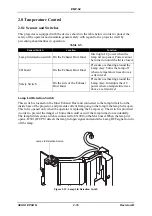
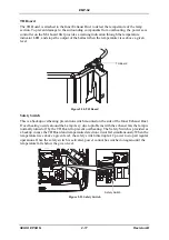
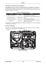
The MA board is connected to the Lamp Thermistor. The driver CPU controls the operation of
the five fans, Intake fan 1, Intake fan 2, Exhaust fan, Power Supply fan and Lamp Fan, based
on the temperatures detected by the thermistor.
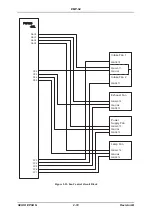
The signals output by IC1102, the driver CPU on the MA board, are used to change the output
from the fan drive regulator circuit on the MA board in order to control Intake and Exhaust
fans. The feedback signals from the fans are used by the CPU to monitor the fan operation
(stopped or running) for any abnormalities. If the feedback signal indicates a condition that the
CPU does not expect, the CPU determines that there is an abnormality in the operation of the
fan and immediately turns off the lamp and causes the warning indicator to light red.
Fan Operation
Standby Mode
Intake Fan (LV/G FAN):
Operates at a constant speed from power-on.
Power Supply Fan
Intake Fan (LV/R FAN):
The rotating speed is adjusted according to preset
temperatures detected by the thermistor.
Exhaust Fan:
Turns on the power supply fan and starts to operate at low
speed when the thermistor detects temperatures higher than
a given level, and stops when the temperature becomes
lower than the level.
Lamp Fan:
The rotating speed is adjusted according to preset
temperatures detected by the thermistor.
When the Lamp is ON
The Intake, Exhaust, and Lamp Fans start to operate at low speed 0.5 second before turning
the lamp on. After the lamp turns on, the fan operates at high speed or low speed based on the
temperatures detected by the thermistor.
During Cool-down
When the lamp is turned off, the fans operate for a few seconds to cool the projector.
Summary of Contents for EMP-S4
Page 1: ...Service Manual Data Projector EMP S4 ...
Page 13: ...Chapter 1 Product Specifications ...
Page 25: ...1 13 EMP S4 SEIKO EPSON Revision B 1 5 External Views Figure 1 8 External Dimensions Unit mm ...
Page 26: ...1 14 EMP S4 SEIKO EPSON Revision B Figure 1 9 External Dimensions Unit Inch ...
Page 27: ...Chapter 2 Theory of Operation ...
Page 49: ...Chapter 3 Troubleshooting ...
Page 63: ...Chapter 4 Disassembly Assembly ...
Page 97: ...Chapter 5 Appendix ...
Page 102: ...5 6 EMP S4 SEIKO EPSON Revision B ...

