background image

Connecting the Printer to Your Computer

If the self test printed correctly, you are ready to connect your
printer to the computer. Most computers have a parallel interface.
To connect such an interface, use a suitable shielded cable as
described in the next section.

The parallel interface

Connect the parallel interface cable as described below:

1.

Make sure 

that 

both your printer and computer are turned off.

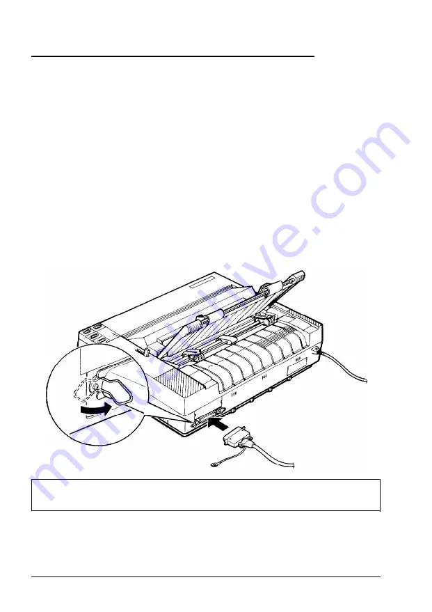
Plug the cable connector securely into the printer. Then
squeeze the wire clips together until they lock in place on
either side of the connector.

Note: If your cable has a ground wire, connect it to the ground
connector beneath the interface connector.

2.

Plug the other end of the cable into the computer. (If there is a
ground wire at the computer end of the cable, attach it to the
ground connector at the back of the computer.)

Setting Up the Printer

1-13

Summary of Contents for ActionPrinter 2000

Page 1: ...U S E R S G U I D E Y46399119002 ...

Page 2: ...iable to the purchaser of this product or third parties for damages losses costs or expenses incurred by purchaser or third parties as a result of accident misuse or abuse of this product or unauthorized modifications repairs or alterations to this product Seiko Epson Corporation and its affiliates shall not be liable against any damages arising from the use of any options other than those designa...

Page 3: ...rom that to which the receiver is connected Consult the dealer or an experienced radio TV technician for help WARNING The connection of a non shielded equipment interface cable to this equipment will invalidate the FCC Certification of this device and may cause interference levels which exceed the limits established by the FCC for this equipment It is the responsibility of the user to obtain and u...

Page 4: ...de an option to set the maximum lines per page If your program has a lines per page setting and you are using standard 8 X 11 inch paper set the lines per page to 61 Note To find the right lines per page setting for paper that is not 8 X 11 create a test document using your application program Set your top and bottom margins to 0 and then create a file of numbered lines from 1 to 66 When you print...

Page 5: ...on Consumer Resource Center at 800 922 8911 Assistance in locating your nearest Authorized Epson Reseller or Service Center Technical assistance with the installation configuration and operation of Epson products Epson technical information library fax service Product literature with technical specifications on our current and new products Sales of ribbons supplies parts documentation and accessor...

Page 6: ...openings should never be blocked by placing the product on a bed sofa rug or other similar surface This product should never be placed near or over a radiator or heat register This product should not be placed in a built in installation unless proper ventilation is provided 7 This product should be operated from the type of power source indicated on the marking label If you are not sure of the typ...

Page 7: ... Remove may expose you to dangerous voltage points or other risks Refer all servicing in those compartments to service personnel 13 Unplug this product from the wall outlet and refer servicing to qualified service personnel under the following conditions A When the power cord or plug is damaged or frayed B If liquid has been spilled into the product C If the product has been exposed to rain or wat...

Page 8: ...Application Software 1 14 Chapter 2 Paper Handling 2 1 Using Single Sheets 2 2 Using Continuous Paper 2 4 Adjusting the Loading Position 2 7 Switching Between Continuous and Single Sheets 2 8 Printing on Special Paper 2 10 Chapter 3 Using the Printer 3 1 Operating the Control Panel 3 2 Setting the DIP Switches 3 5 Selecting Typestyles 3 9 Selecting an International Character Set 3 11 Choosing a Ch...

Page 9: ...ms and Solutions 6 2 Power Supply 6 3 Printing 6 4 Paper Handling 6 8 Options 6 10 Chapter 7 Technical Specification 7 1 Printer Specifications 7 2 Interface Specifications 7 7 Initialization 7 10 Chapter 8 Command Summary 8 1 Using the Command Summary 8 2 Commands Arranged by Topic 8 3 Appendix A 1 Character Tables A 2 Glossary GL 1 V l l l ...

Page 10: ...ducing high quality documents A convenient control panel design that allows direct selection of fonts as well as a choice of normal or condensed printing The SmartParkTM paper handling system that lets you use single sheets of paper without removing continuous paper eliminates paper waste with short tear off and allows easy and accurate paper alignment Compatibility with the Epson ESC P commands u...

Page 11: ...rms Roll Paper Holder 8310 The optional roll paper holder allows you to use the many different types of 21 6 cm or 8 inch roll paper sold for telexes and similar machines Interface Boards Optional interface boards are available to supplement the printer s built in parallel interface Guidelines for choosing the right interface are given in Chapter 4 Finding Your Way Around This manual provides illu...

Page 12: ...ns l Other chapters contain information on general maintenance specifications and printer commands There is also a glossary of printer terms and an index Warnings Cautions and Notes WARNINGS must be followed carefully to avoid bodily injury CAUTIONS must be observed to avoid damage to your equipment Notes contain important information and useful tips on the operation of your printer Introduction 3...

Page 13: ...oduction Names of the Parts paper guide printer control panel release paper tension unit cover ribbon cartridge A C i n l e t Note In some locations the power cord is attached to the printer 4 Introduction ...

Page 14: ... the platen knob 1 5 Installing the ribbon cartridge 1 6 Attaching the paper guide 1 9 Testing the Printer 1 10 Plugging in the printer 1 10 Running the self test 1 10 Connecting the Printer to Your Computer 1 13 The parallel interface 1 13 Setting Up Your Application Software 1 14 Choosing from a menu 1 14 Setting Up the Printer l l ...

Page 15: ...oving the parts save the packaging materials in case you ever need to transport your printer CAUTION There are several different versions of the printer designed for different electrical standards It is not possible to adjust the printer for use at another voltage The power supply type is shown on the label on the back of the printer If it does not show the correct voltage for your country contact...

Page 16: ...ect sunlight excessive heat moisture or dust Use a grounded outlet do not use an adapter plug Avoid electrical outlets controlled by wall switches or automatic timers Accidental interruption of power can wipe out information in the memory of your computer or your printer Avoid outlets on the same circuit with large motors or other appliances that might cause fluctuations in line voltage Keep the e...

Page 17: ...ep your printer absolutely level If you position the paper supply below the printer stand make sure that you allow enough clearance 25 mm or 1 inch to keep the paper from catching on the underside of the stand Also see that the distance between the stand s supports is at least 280 mm 11 inches to accommodate any paper size you may use Position your printer s power cord and interface cable so that ...

Page 18: ...to manually feed paper in the printer when the printer is turned off You will find the platen knob packed in an indentation in the white foam packaging material 1 Insert the knob into the hole on the printer s side and rotate it slowly until it slips onto the shaft 2 Push firmly on the platen knob until it fits against the printer case Setting Up the Printer 1 5 ...

Page 19: ...bbon cartridge make sure that the printer is not plugged into an electrical outlet 1 Raise the printer cover to the upright position Then lift the cover up and off 2 Slide the print head to the middle of the printer Then open the paper tension unit cover 1 6 Setting Up the Printer ...

Page 20: ...ack from the ribbon making it easier to install 4 Hold the ribbon cartridge by its handle and push it firmly down into position making sure the plastic hooks fit into the slots Note Press lightly on both ends of the cartridge to make sure the plastic hooks are properly seated Setting Up the Printer 1 7 ...

Page 21: ...on between the print head and ribbon guide while you turn the ribbon tightening knob to help feed the ribbon into place 6 Slide the print head from side to side to make sure that it moves smoothly Also check that the ribbon is not twisted or creased 7 Close the paper tension unit cover 1 8 ...

Page 22: ...Assembling the Printer Attaching the paper guide 1 Place the paper guide on the printer Then raise it up until it locks into place 2 Attach the printer cover Setting Up the Printer 1 9 ...

Page 23: ...r outlet voltage do not match contact your dealer for assistance Do not plug in the power cord 3 If necessary connect the power cord to the AC inlet on the printer s back panel 4 Plug the power cord into a properly grounded electrical outlet Running the self test The self test runs in draft or Near Letter Quality NLQ mode depending on which button you hold down as you turn on the printer 1 Make su...

Page 24: ...ge guide to match the width of 4 Slide a sheet of paper down firmly between the edge guides until it meets resistance CAUTION Run the self test using paper wider than A4 210 mm or 8 inches or letter size 216 mm or 81 2 inches to prevent the print head from printing directly on the platen Setting Up the Printer 1 11 ...

Page 25: ...seconds before turning it back on Turning the power on and off rapidly can damage the printer Here is part of a typical self test printed in Near Letter Quality mode 0 1 2 3 4 5 6 7 8 9 A B C D E F G H I J K r 0 1 2 3 4 5 6 7 8 9 A B C D E F G H I J K L 0 1 2 3 4 5 6 7 8 9 A B C D E F G H I J K L M 0 1 2 3 4 5 6 7 8 9 A B C D E F G H I J K L M N 1 0 1 2 3 4 5 6 7 8 9 A B C D E F G H I J K L M N O ...

Page 26: ...escribed below 1 Make sure that both your printer and computer are turned off Plug the cable connector securely into the printer Then squeeze the wire clips together until they lock in place on either side of the connector Note If your cable has a ground wire connect it to the ground connector beneath the interface connector 2 Plug the other end of the cable into the computer If there is a ground ...

Page 27: ...rinter on its printer selection menu If your printer is not listed choose from the following list The printers are listed in the order of preference LX 810 850 LX 800 LX 86 LX 80 FX 850 FX 86e EX 800 FX 85 FX 80 FX 80 If none of these printers is listed select the first one available on the following list LX FX EX RX MX Epson printer Standard printer Draft printer To use all of the features of the...

Page 28: ...your continuous paper supply 2 4 Loading continuous paper 2 4 Adjusting the Loading Position 2 7 Switching Between Continuous and Single Sheets 2 8 Switching to single sheets 2 8 Switching back to continuous paper 2 9 Printing o n Special Paper 2 10 T h e paper thickness lever 2 10 Multi part forms 2 11 Labels 2 11 Envelope 2 12 Paper Handling 2 1 ...

Page 29: ...1 Turn off the printer then place the paper guide in the upright position Set the paper release lever to the single sheet position 2 Turn on the printer The POWER and PAPER OUT lights come on 3 Slide the left edge guide until it locks in place at the guide mark Next adjust the right edge guide to match the paper width 2 2 Paper Handling ...

Page 30: ...n and then press the FORM FEED button Printing multiple page documents When you print a document of more than one page using single sheet paper you must reload paper at the end of each page To reload first see that the printer is off line If the ON LINE light is on press the ON LINE button once to take the printer off line Then load a new sheet by following steps 4 5 and 6 above If your software h...

Page 31: ...rinter and supply of continuous paper Make sure you align your paper supply with the paper loaded in the tractor so that the paper feeds smoothly into the printer Loading continuous paper 1 Make sure the printer is turned off Then remove the paper guide and pull the paper release lever forward to the continuous paper position 2 Release the sprocket units by pulling the sprocket locks forward 2 4 P...

Page 32: ...n slide the right sprocket unit to match the width of your paper but do not lock it 4 Move the paper support midway between the two sprocket units 5 Open both sprocket covers Fit the first three holes in the paper over the pins of both sprockets CAUTION Make sure that your paper has a clean straight edge before inserting it into the printer Paper Handling 2 5 ...

Page 33: ...Press the ON LINE button to set the printer on line The printer remembers the loading position and advances each page to the same position If you need to adjust the loading position use the micro adjustment feature See the section on adjusting the loading position in Chapter 3 CAUTION Use the platen knob only when the printer is off and there is a paper feeding problem such as a paper jam Otherwis...

Page 34: ...tion always use the following 1 Make sure that the printer is turned on and that paper single sheet or continuous is ready for loading 2 Press the LOAD EJECT button to feed paper to the loading position Then press and hold down the ON LINE button until the beeper sounds once and the ON LINE light begins to blink 3 Press the FORM FEED button to feed the paper forward or the LINE FEED button to feed...

Page 35: ... 4 5 6 7 6 inches wide you should only press the LOAD EJECT button once Also do not use this button to eject labels Never feed labels backward through the printer Labels can easily come off the backing sheet and jam the printer Push the paper release lever back to the single sheet position Stand the paper guide upright and move the left edge guide so that it locks in place next to the guide mark A...

Page 36: ...the edge guides together so that they meet at the center of the paper s width Lower the paper guide onto the back of the printer Pull the paper release lever forward to the continuous paper position Press the LOAD EJECT button to feed the continuous paper to the loading position Press the ON LINE button to set the printer on line so it can accept data Paper Handling 2 9 ...

Page 37: ...ur printer can also print on a wide variety of paper types such as labels and multi part forms Before printing on special types of paper you may need to change the paper thickness setting The paper thickness lever For normal use set the paper thickness lever to position 2 2 10 Paper Handling ...

Page 38: ... of up to three parts including the original Make sure you set the paper thickness lever to the proper position using the table above Labels When printing labels always choose the type mounted on a continuous backing sheet with sprocket holes for use with a tractor CAUTION l Never feed labels backward through the printer Labels can easily peel off the backing and jam the printer l Since labels are...

Page 39: ... use envelopes under normal operating condition Note Always set the paper thickness lever to the position indicated for envelopes in the paper thickness lever section in this chapter Always feed envelopes by inserting the wide edge into the printer Make sure your application software keeps the printing within the printable area of the envelopes you are using 2 12 Paper Handling ...

Page 40: ... control panel features 3 4 Setting the DIP Switches 3 5 Changing a DIP switch setting 3 5 DIP switch settings 3 6 DIP switch functions 3 7 Selecting Typestyles 3 9 Character fonts 3 9 Condensed mode 3 10 Selecting an International Character Set 3 11 Choosing a Character Table 3 12 Using the Printer 3 1 ...

Page 41: ...inting PAPER OUT red On when the printer is out of paper or when continuous paper is in the standby position The printer also beeps when it is out of paper ON LINE green On when the printer can receive and print data from the computer When this light is blinking you can use the micro adjustment feature Buttons ON LINE This button controls the printer s on line off line status When the printer is o...

Page 42: ...er ejects paper forward if the paper release lever is set to the single sheet position it ejects paper backward removes it from the paper path if the release lever is set to the continuous paper position SelecType When the printer is on line you use the FORM FEED LINE FEED and LOAD EJECT buttons to select the printer s built in character fonts NLQ Press this button to select the NLQ Roman and NLQ ...

Page 43: ...sting the printer in Chapter 1 for more information Micro adjustment The micro adjustment function allows you to make fine adjustments to the loading and short tear off positions See the section on adjusting the loading position in Chapter 2 and the section on using short tear off later in this chapter Data dump The data dump mode allows advanced users to find the cause of communication problems b...

Page 44: ...h These new settings become effective whenever the printer is turned on reset or initialized Changing a DIP switch setting 1 Turn off the printer 2 Use a pointed instrument such as the tip of a pen to turn a switch on or off The tables on the following pages give the DIP switch functions for each setting The new DIP switch settings take effect when the printer is turned on Using the Printer 3 5 ...

Page 45: ...our self test printout See Table 1 characters and See Table 2 DIP Switch 2 ON OFF 2 1 Short tear off Invalid Valid 2 2 Cut sheet feeder mode ON OFF 2 3 Skip over perforation ON OFF 2 4 Auto line feed ON OFF Table 1 Page length Page length SW1 3 SW1 4 11 inches OFF OFF 12 inches ON OFF 8 5 inches OFF ON 11 7 inches ON ON 3 6 Using the Printer ...

Page 46: ...pacing of 10 cpi characters per inch if it is on the printer prints with character spacing of 12 cpi T h i s i s 1 0 c p i p r i n t i n g ABCDEFGHIJKLabcdefghijkl This is 12 cpi printing ABCDEFGHIJKL cdefghijkl Shape of zero When DIP switch 1 2 is on the printer prints slashed zeros 0 when off the printer prints open zeros 0 Page length DIP switches 1 3 and 1 4 control the page length You can sel...

Page 47: ...ure is turned on and that the paper is in the short tear off position 2 Press and hold the ON LINE button until the printer beeps once and the ON LINE light begins blinking 3 Press the FORM FEED button to feed the paper forward or the LINE FEED button to feed it backward When you resume printing the ON LINE light stops blinking and the printer remembers the new tear off position even after you tur...

Page 48: ... printing which makes it ideal for rough drafts and editing work NLQ Roman and NLQ Sans Serif are Near Letter Quality fonts Near Letter Quality produces nicely formed characters suitable for most documentation needs To select the draft font press the DRAFT LINE FEED button when the printer is on line When you select the draft font the beeper sounds once To select the NLQ font press the NLQ FORM FE...

Page 49: ...n the condensed mode characters are approximately 60 of the width of normal characters You can condense both 10 and 12 cpi in draft mode but not NLQ To select or cancel condensed mode press the CONDENSED LOAD EJECT button when the printer is on line When you select the condensed mode the printer beeps once When you cancel the condensed mode the printer beeps twice 3 10 Using the Printer ...

Page 50: ...you can select with DIP switches 1 6 1 7 and 1 8 when DIP switch 1 5 is turned off The table also shows the characters that differ in each set Note If you wish to select an international character set when DIP switch 1 5 is turned on use the ESC R command Besides the eight sets above the five international character sets shown below are also available through the ESC R command Using the Printer 3 ...

Page 51: ...For italics see your software manual or the description of the ESC 4 command in the Command Summary Chapter 8 You can also select the italics character set or a graphics character set using the ESC t command See the Command Summary in Chapter 8 Graphics character sets Settings not shown above select PC 437 United States The characters in each character set are shown in the Appendix Note To change ...

Page 52: ... Single sheet insertion 4 7 Removing the cut sheet feeder 4 8 Pull Tractor 4 9 Installing the pull tractor 4 9 Paper handling 4 1 0 Removing the pull tractor 4 1 2 Roll Paper Holder 4 1 4 Installing the roll paper holder 4 1 4 Paper handling 4 1 5 Removing the roll paper holder 4 1 6 Interface Boards 4 1 7 Installing an interface board 4 1 7 Using the Printer Options 4 1 ...

Page 53: ...omatically Installing the cut sheet feeder 1 Make sure that the printer is turned off Remove the paper guide and printer cover If the pull tractor is installed remove it 2 Separate the two halves of the printer cover by pressing on the tabs and pulling off the clear plastic half of the printer cover 3 Attach the cut sheet feeder cover to the front half of the printer cover 4 2 Using the Printer Op...

Page 54: ...ion 5 Hold the assembled cut sheet feeder in both hands and fit its notches over the pins of the printer 6 Attach the cut sheet feeder cover to the printer 7 Turn on the cut sheet feeder mode by setting DIP switch 2 2 to on 8 Turn on the printer Using the Printer Options 4 3 ...

Page 55: ...per loading 2 Slide the left paper guide to where the fin on the edge guide aligns with the arrow on the front panel Next slide the right 3 Take a stack of paper and fan it Tap the side and bottom of the paper on a flat surface to even up the stack CAUTION Do not use multi part forms carbon paper or labels in the cut sheet feeder 4 4 Using the Printer Options ...

Page 56: ...nst the guide rollers A new sheet of paper loads automatically whenever a printable character or line feed command is sent to the printer while the ON LINE light is on Note Run the self test in the cut sheet feeder mode The printer counts the number of lines on the page in l 6 inch line spacing and prints out this number at the bottom of the first test page Use this number to set the lines per pag...

Page 57: ...fold the first printed page forward after the perforation passes the printer cover edge Switching to the cut sheet feeder 1 If any printed sheets remain in the printer press the ON LINE button to set the printer off line then press the FORM FEED button to advance any printed continuous paper 2 Tear off the printed pages 3 Press the LOAD EJECT button The printer feeds the continuous paper backward ...

Page 58: ...ent type or size of paper for one sheet only without replacing the stack of paper in your cut sheet feeder 1 Press the ON LINE button to set the printer off line 2 Align the single sheet to be fed with the mark on the left paper guide then slide the sheet into the printer path until you feel resistance 3 Press the LOAD EJECT button to load the sheet Using the Printer Options 4 7 ...

Page 59: ...e its notches from the pins in the printer and remove the cut sheet feeder 4 Separate the cut sheet feeder cover from the printer cover and replace the back half of the printer cover 5 Install the paper guide and printer cover 6 Turn off the cut sheet feeder mode by setting DIP switch 2 2 to off Be sure to store the removed cut sheet feeder in its original box and packing materials 4 8 Using the P...

Page 60: ...ctor as described in this section Do not use short tear off with the pull tractor Installing the pull tractor 1 Turn off the printer Then remove the printer cover and paper guide 2 Remove the paper tension unit cover 3 Fit the tractor unit s rear notches over the rear mounting pins of the printer Then tilt the tractor unit forward until its front latches lock onto the printer s front mounting pins...

Page 61: ...dvance the paper one page for fitting onto the pull tractor CAUTION If you use the platen knob to feed the paper the printer loses track of the top of form position Be sure to press the LINE FEED or FORM FEED button to feed paper 4 5 6 Open the pull tractor sprocket covers and release the sprocket units by pulling the sprocket locks forward Adjust the sprocket units to match the width of the paper...

Page 62: ...er fits properly Make sure that the paper release lever is set forward to the continuous paper position I CAUTION Make sure that the pull tractor s sprocket units are aligned with those of the built in push tractor 9 Separate the two halves of the printer cover by pressing on the tabs and pulling off the clear plastic half Using the Printer Options 4 11 ...

Page 63: ... Instead of setting the paper on the pins of the push tractor simply insert it through the same paper path as you would use with single sheet paper Removing the pull tractor 1 If you have a printed document in the printer set the printer off line and press the FORM FEED button to feed the paper forward Then tear off the document at the perforation 2 Press the ON LINE button to set the printer off ...

Page 64: ...notches of the unit are free back 5 Lift the tractor unit up and off 6 Reinstall the paper tension unit cover 7 Separate the tractor cover from the printer cover and replace the clear plastic half of the printer cover 8 Install the paper guide and printer cover Push the paper release lever to the single sheet position Using the Printer Options 4 13 ...

Page 65: ... guide 2 Position the roll paper holder beneath the printer as shown below Fit the two holes in the base onto the two positioning pegs on the bottom of the printer 3 Push the paper release lever to the single sheet position CAUTION Only the weight of the printer holds the roll paper holder in place The positioning pegs only prevent the holder from slipping out of position If you pick up the printe...

Page 66: ...lder shaft through the center of the paper roll 4 Set the shaft and paper roll onto the roll paper holder Orient the roll so that paper feeds from the bottom of the roll Then turn on the printer 5 Bring the leading edge of the paper up over the paper path guide and insert it into the printer path until you feel resistance 6 Press the LOAD EJECT button to load the paper Using the Printer Options 4 ...

Page 67: ...ar off the paper against the tear off edge of the printer cover Removing the roll paper holder 1 Cut across the paper behind the point where it feeds into the printer Then use the LOAD EJECT button to eject any paper remaining in the printer 2 Turn off the printer 3 Remove the paper roll and shaft from the roll paper holder 4 Lift up the printer and separate the roll paper holder from the printer ...

Page 68: ... 8 1 4 3 New Serial interface 8148 Intelligent serial interface 8165 Intelligent IEEE 488 interface To learn more about interfaces contact your Epson dealer Installing an interface board The following sections describe how to install an interface board Removing the upper case CAUTION Use caution when removing or attaching the upper case to avoid damaging the printer 1 Turn off the printer and remo...

Page 69: ...s using a pointed object 5 To remove the upper case first position the printer so that its front extends slightly over the edge of a table allowing access to the openings on the front of the underside of the printer CAUTION Make sure that the printer is not so far forward that it is in danger of falling off the table 4 18 Using the Printer Options ...

Page 70: ... the handle of the screwdriver toward the back of the printer to release the clips on the case 7 Partially raise the upper case taking care not to strain the flat cable attached to the control panel 8 Carefully disconnect the flat control panel cable from the connector labelled CN3 on the main board Using the Printer Options 4 19 ...

Page 71: ...ard then remove it from the printer 10 Remove the shield plate by pressing in on the plastic clips located at the back of the plate 11 Using a cross head screwdriver remove the screw labelled CG from the main board 4 20 Using the Printer Options ...

Page 72: ...his slight difference changes the way the boards are installed in the printer but does not affect the operation of the interface in any way Check below to see which type of interface board you have FG wire not attached FG wire attached 1 Use the CG screw to attach the round end of the FG frame ground wire to the main board Using the Printer Options 4 21 ...

Page 73: ...connector on the main board then secure the board with the three screws provided FG wire not attached FG wire attached 3 If the FG wire is not attached to the interface board attach the plug end of the FG wire onto the FG pin located on top of the interface board 4 22 Using the Printer Options ...

Page 74: ...o 9600 BPS Bits Per Second Make sure you use the bit rate selection table for printers with buffers in the 8143 interface manual 5 Reattach the upper case as described next Attaching the upper case 1 Fit the hinges of the upper case into the openings in the lower case then partially lower the upper case CAUTION Take care not to pinch the FG wire between the upper and lower cases Using the Printer ...

Page 75: ... it locks into place 4 Reattach the push feed tractor 5 Reattach the ribbon cartridge paper tension unit cover and platen knob CAUTION When you install an optional interface board be sure to disconnect the printer cable from the printer s built in parallel interface You must not connect two interface cables to the printer at the same time I I 4 24 Using the Printer Options ...

Page 76: ...Chapter 5 Maintenance Cleaning the Printer 5 2 Replacing the Ribbon 5 3 Transporting the Printer 5 4 Maintenance 5 1 ...

Page 77: ...clean cloth dampened with a mild detergent solution Keep the printer cover in place to prevent water from getting inside the printer CAUTION Never use alcohols or thinners to clean the printer since these chemicals can damage the components as well as the case Be careful not to get the printer mechanism or electronic components wet Do not use a hard or abrasive brush Do not spray the inside of the...

Page 78: ...replace the ribbon Use only the Epson 8750 standard ribbon cartridge with your printer See Installing the ribbon cartridge in Chapter 1 WARNING If the printer has just been used the print head may be hot Let it cool before attempting to replace the ribbon Maintenance 5 3 ...

Page 79: ...d below 1 2 3 4 5 6 Turn off the printer Remove the paper guide printer cover and any installed options Unplug the power cord from the electrical outlet then disconnect the interface cable from the printer Remove the ribbon cartridge and platen knob Reattach the printer cover Replace the packing materials and put the printer in its box 5 4 M a i n t e n a n c e ...

Page 80: ...Chapter 6 Troubleshooting Problems and Solutions 6 2 Power Supply 6 3 Printing 6 4 Paper Handling 6 8 Options 6 10 Troubleshooting 6 1 ...

Page 81: ... the printed characters or graphics See 6 5 Printed characters are not what you expected See 6 5 The print position is not what you expected See 6 6 Paper handling Single sheets do not feed properly Continuous paper does not feed properly See 6 8 See 6 9 Options When you use the cut sheet feeder the paper does not feed properly See 6 10 Switching between the cut sheet feeder and the push tractor d...

Page 82: ...timer use a different outlet Plug another electrical device into the outlet to determine whether the outlet is operating properly l The POWER light comes on briefly and then goes off The light stays off even when the power is turned on again Check that the printer s voltage rating matches the voltage of your electrical outlet If the voltages do not match unplug the printer and contact your dealer ...

Page 83: ...s Check both ends of the interface cable between the printer and the computer Make sure your interface cable meets both the printer and computer specifications The PAPER OUT light is on Load paper into the printer If paper is already loaded the paper may be set too far to the right for detection by the paper sensor Move the paper a little to the left The printer sounds like it is printing but noth...

Page 84: ...ot be installed properly See the section on ribbon installation in Chapter 1 The printout is faint The ribbon may be worn out Replace the ribbon cartridge Check that the paper thickness lever is set correctly for the paper you are using Dots are missing in the printed characters or graphics l A line of dots is missing in the printout The print head is damaged Stop printing and contact your dealer ...

Page 85: ...may be selected Check the DIP switch settings See the section on DIP switches in Chapter 3 Also you may be using the wrong cable or your cable may not be properly connected The print position is not what you expected Printing starts too high or too low on the page Adjust the top margin set by your application software All the text is printed on the same line Set DIP switch 2 4 off Page length does...

Page 86: ...apter 3 Make sure the DIP switch settings match your required paper length See the section on DIP switches in Chapter 3 If your application program is setting the top and bottom margins set DIP switch 2 3 off If the printer still does not print correctly try the self test described in Chapter 1 If the self test works properly the printer is all right and the problem probably lies in the computer t...

Page 87: ...er when you choose a printer from your application program s menu See Chapter 1 If possible specify single sheet paper with your application software Use your application software to reduce or eliminate the top margin and reduce the page length When you press the LOAD EJECT button the platen does not rotate and paper does not feed If the ON LINE light is on press the ON LINE button once to set the...

Page 88: ...rward to the continuous paper position Make sure that the paper supply is not obstructed by a cable or some other object Make sure that your paper supply is positioned within 1 meter 3 feet of the printer The position of your paper supply may be preventing it from feeding straight See that the holes on the sides of the paper are aligned with each other Also make sure the sprocket units are locked ...

Page 89: ...The cut sheet feeder may be incorrectly installed on the printer See that the paper release lever is pushed back to the single sheet position You may have loaded too many sheets in the cut sheet feeder s bin Paper may be jammed near the print head There may be only one sheet left in the bin Add more paper Two or more sheets feed at one time You may have loaded too many sheets in the cut sheet feed...

Page 90: ...aper type does not load The paper release lever may not be in the proper position Pull the lever forward to load continuous paper or push the lever back to load single sheets When you change the paper release lever position the printer beeps continuously You may have changed the paper release lever position while paper was in the paper path Return the paper release lever to its former position and...

Page 91: ...e caught on the edge guides Make sure that the paper guide is installed over the paper and that the edge guides are positioned at the center of the paper s width The pull tractor and push tractor sprockets are not aligned correctly When using both tractors be sure that the sprockets on both are positioned evenly The paper may have too much slack Adjust the position of the sprockets to take up any ...

Page 92: ...ntrol codes ESC C or ESC C 0 to set the correct page length The loading position of the paper may be too high or too low Use the microadjustment feature to reset the loading position When printing ends the paper feeds abruptly and as it resumes printing the paper feeds backward and comes off the pull tractor sprockets You may have selected the short tear off which you cannot use with the pull trac...

Page 93: ...to the single sheet position The position of the roll paper may be wrong Position the paper roll so that the paper feeds off of the bottom of the roll The paper feed is crooked or the paper jams The roll paper holder may be installed incorrectly Check that the holes in the base fit onto the two corresponding pegs at the bottom of the printer The shaft with the paper roll may not be properly mounte...

Page 94: ...roperly l The printer does not print or the printout is not what you expected The interface board may be loose or not properly connected Check that the interface board is correctly inserted into the connector on the main board You may not be using the correct interface Check the specifications to make sure that you can use the interface with this printer You may not be using the correct cable Make...

Page 95: ...ecifications 7 2 Printing 7 2 Paper 7 3 Mechanical 7 5 Electrical 7 6 Environmental 7 6 Interface Specifications 7 7 Specifications and pin assignments 7 7 Interface timing 7 9 Initialization 7 10 Default settings 7 10 Technical Specification 7 1 ...

Page 96: ...roper software command Line spacing l 6 inch l 8 inch or programmable in increments of l 216 inch Paper feed speed 75 ms line at l 6 inch line spacing with continuous feeding 95 ms line with intermittent feeding Printable columns 80 characters at 10 cpi 96 characters at 12 cpi 137 characters at 10 cpi condensed 160 characters at 12 cpi condensed Buffer 4KB Character fonts Draft Epson NLQ Roman Eps...

Page 97: ... Labels continuous only 63 5 X 23 8 mm 2 l 2 X 15 16 inches minimum Paper length Single sheet 364 mm 14 3 inches maximum Printable area Single sheet and Roll paper 8 5 m m 0 3 3 o r m o r e 5 0 m m 1 9 7 o r more 3 m m 0 1 2 o r m o r e 3 m m O 1 2 or more Printable area 1 3 5 m m 0 5 3 o r m o r e 6 0 m m 2 3 6 o r m o r e Roll paper Technical Specification 7 3 ...

Page 98: ...more right side when the 254 mm 10 inch width paper is used Envelope I 8 5 m m 2 2 m m 0 3 3 0 8 7 I 3 m m 0 1 2 or more or more Paper thickness Single sheet 0 065 to 0 140 mm 0 0025 to 0 0055 Continuous paper 0 065 to 0 250 mm 0 0025 to 0 0098 Roll paper 0 070 to 0 090 mm 0 0028 to 0 0035 Envelope 0 160 to 0 520 mm 0 0063 to 0 0197 Label 0 160 to 0 190 mm 0 0063 to 0 0075 including the base sheet...

Page 99: ...ies Maximum thickness 0 25 mm 0 01 inch Note Print on 90 g m2 24 lb paper only at normal temperature Printing on labels made of pressure sensitive paper jointed by perforations or pasting and with a total thickness of up to 0 3 mm 0 012 is possible only when temperature is between 5 C to 35 C and 10 to 80 relative humidity Mechanical Paper feed methods Friction Push tractor Pull tractor optional C...

Page 100: ...chassis Environmental Temperature Width 418 mm 16 5 inches Depth 339 mm 13 3 inches Height 141 mm 5 6 inches Weight Approx 5 8 kg 12 8 lb 120 V AC 10 120 V model Approx 28 W during self test printing in draft mode 50 0 0 5 Hz 60 0 0 5 Hz 10 Ma between AC power line and chassis 120 V model can withstand 1 0 kV rms applied for one minute Operation 5 C to 35 C 41 F to 95 F Storage 30 C to 6O C 22 F t...

Page 101: ...ection Description 1 19 STROBE IN STROBE pulse to read data Pulse width must be more than 0 5 µsec at the receiving terminal 2 20 DATA 1 IN These signals represent information of 3 21 DATA 2 IN the 1st to 8th bits of parallel data 4 22 DATA 3 IN respectively 5 23 DATA 4 IN Each signal is at HIGH level when data 6 24 DATA 5 IN is logical 1 and LOW when it IS logical 0 7 25 DATA 6 IN 8 26 DATA 7 IN ...

Page 102: ...Interface Specifications 7 8 Technical Specification ...

Page 103: ...round level Be sure to use a twisted pair for each signal and to complete the connection on the return side Cables should be shielded and connected to the chassis of the host computer and the printer Interface timing The figure below shows the timing for the parallel interface B U S Y A C K N L G I D A T A STROBE Technical Specification 7 9 ...

Page 104: ... shows the default conditions that become effective when the printer is initialized Item Default condition Too of form position Current paper position Page length Left and right margins Line spacing The current DIP switch setting Canceled 1 6 inch Vertical tab position Horizontal tab positions Font selection Special printing effects Cleared Every eight characters The current SelecType setting Canc...

Page 105: ...Topic 8 3 Printer operation 8 3 Data control 8 3 Vertical motion 8 4 Horizontal motion 8 5 Overall printing style 8 6 Print size and character width 8 6 Print enhancement 8 7 W o r d processing 8 8 Character tables 8 8 User defined characters 8 9 Graphics 8 9 Command Summary 8 1 ...

Page 106: ... explained The parameters are indicated by lowercase italicized letters usually n The examples below show how the parameters are indicated ESC is a command with no parameters ESC U 1 O is a command that uses 1 to turn the feature on and 0 to turn it off ESC n1 n2 is a command with two parameters ESC D nn is a command with a variable number of parameters 8 2 Command Summary ...

Page 107: ...On Off Select Unidirectional Mode one line Turn Unidirectional Mode On Off Disable Paper Out Detection Enable Paper Out Detection Turn Cut Sheet Feeder Mode On Off 4 Turns mode on 0 Turns mode off Note For the ESC EM command the variables are the characters 0 48 decimal or 30 hex and 4 52 decimal or 34 hex Do not use 0 decimal 00 hex 4 decimal or 04 hex BEL 7 07 Beeper Data control ASCII D e c H e...

Page 108: ...43 78 4E 79 4F 10 OA 48 30 49 31 50 32 51 33 65 41 74 4A 11 OB Form Feed Set Page Length in Lines n no of lines 1 127 Set Page Length in Inches n no of inches l 22 Set Skip Over Perforation n no of lines l 127 Cancel Skip Over Perforation Line Feed Select l 8 inch Line Spacing Select 7 72 inch Line Spacing Select l 6 inch Line Spacing Select n 216 inch Line Spacing Select n 72 inch Line Spacing Pe...

Page 109: ... Channel ASCII D e c H e x D e s c r i p t i o n ESC 1 n 108 6 C ESC Q n 81 51 BS 8 08 ESC e 0 n 101 6 5 ESC e 1 n ESC f 0 n 101 102 102 6 5 ESC f 1 n 6 6 66 Set Left Margin n left margin column Set Right Margin n right margin column Backspace Set Horizontal Tab Increments n horizontal tab interval in spaces n 21 at 10 cpi 25 at 12 cpi or 36 in condensed modes Set Vertical Tab Increments n vertica...

Page 110: ...k n 107 ESC n 33 7 8 Select NLQ or Draft 1 NLQ 0 Draft 6B Select NLQ Font 0 Roman l Sans Serif 21 Master Select To find the value of n add together the numbers of the typestyles you want to combine from the list below 10 cpi 0 decimal 0 0 hex 12 cpi 1 01 condensed 4 04 emphasized 8 08 double strike 16 1 0 double width 32 20 italics 64 40 underline 128 80 Print size and character width ASCII D e c ...

Page 111: ...e Cancel Double Width Mode one line Turn Double Width Mode On Off Print enhancement ASCII Dec Hex Description ESC E 69 ESC F 70 ESC G 71 ESC H 72 ESC So 83 ESC S1 83 ESC T 84 ESC 4 52 ESC 5 53 ESC l o 45 45 Select Emphasized Mode 46 Cancel Emphasized Mode 47 Select Double Strike Mode 48 Cancel Double Strike Mode 53 Select Superscript Mode 53 Select Subscript Mode 54 Cancel Superscript Subscript Mo...

Page 112: ...D e c H e x D e s c r i p t i o n ESC t n 116 74 Select Character Tables Selects character table for codes 128 255 0 Italic l Graphics ESC R n 82 52 Select an International Character Set 0 USA 1 France 2 Germany 3 UK 4 Denmark I 5 Sweden 6 Italy 7 Spain I 8 Japan 9 Norway 10 Denmark II 11 Spain II 12 Latin America ESC 6 ESC 7 54 36 Printable Code Area Expansion 55 37 Enable Upper Control Codes 8 8...

Page 113: ...ing defined In NLQ mode 3 bytes required for each of 11 columns of each character being defined ESC On 0 58 3A Copy ROM into RAM 0 Roman l Sans Serif ESC O l 37 25 Select User Defined Set 0 Normal set l User defined set Graphics ASCII D e c H e x D e s c r i p t i o n E S C K n 1 n 2 7 5 4 B Select Single Density Graphics Mode Total columns nl n2 X 256 E S C L n 1 n 2 7 6 4 C Select Double Density...

Page 114: ...s in Single density ESC K 0 60 Double density ESC L 1 120 High speed double density ESC Y 2 120 Quadruple density ESC Z 3 240 CRT I none 4 80 Plotter 1 1 none 5 72 CRT II I none Adjacent dots cannot be printed in this mode ESC s n2 63 3F Reassign Graphics Mode s is character K L or Z to be reassigned to mode n O 6 ESC A m nl n2 94 5E Select 9 Pin Graphics Mode m Print density 0 for single 1 for do...

Page 115: ...Appendix Character Tables A 2 Italic character table A 2 Graphics character tables A 3 Appendix A 1 ...

Page 116: ...1 6 l 7 and l 8 or using the ESC t software command For the graphics character tables the ESC 6 and ESC 7 software commands let you select whether hex codes 80 to 9F are characters ESC 6 or control codes ESC 7 Italic character table CODE 0 1 2 3 4 5 6 7 8 9 A B C D E F A 2 Appendix ...

Page 117: ...hics character tables PC 437 United States CODE 0 1 2 3 4 5 6 7 8 9 A B C D E F I 0 1 2 3 4 5 6 7 8 9 A B C D E F PC 850 Multilingual CODE 0 1 2 3 4 5 6 7 8 9 A B C D E F 0 1 2 3 4 5 6 7 8 9 A B C D E F A p p e n d i x A 3 ...

Page 118: ...Character Tables PC 860 Portugal PC 863 Canada French A 4 Appendix ...

Page 119: ...Character Tables PC 865 Norway A p p e n d i x A 5 ...

Page 120: ...expressed in bits per second or bps bidirectional printing Printing in which the print head alternates printing a line from left to right with printing from right to left This increases the overall printing speed because the head prints in both directions character set A collection of letters numbers and symbols that provides you with the characters used in a particular language character table A ...

Page 121: ... switches Small switches in the printer that control various printer functions and set the default status of the printer when it is turned on or initialized DIP stands for Dual In line Package dot matrix A method of printing in which each letter or symbol is formed by a pattern matrix of individual dots double height printing Printing in which each character is twice as tall as normal double strik...

Page 122: ... form feed Refers to both a control code and a panel button that advances the paper to the top of the next page initialize To establish the initial default status of the printer by turning the printer on or by sending an INIT signal interface The connection between the computer and the printer A parallel interface transmits data one character or code at a time and serial interface transmits data o...

Page 123: ...ff and on top of form The position on the paper that the printer recognizes as the first printable line The printer feeds the paper to this position when it loads the paper unidirectional printing Printing in one direction only Allows more precise vertical alignment than bidirectional printing Often used for printing graphics user defined characters Characters that are defined and stored in the pr...

Page 124: ... Connecting printer 1 13 Continuous feed paper 2 5 10 loading 2 5 7 top of form 2 8 Control panel 3 2 5 buttons 3 3 lights 3 2 Cut sheet feeder 3 7 installing 4 2 4 paper handling 4 4 6 removing 4 7 D Data dump 3 5 Default settings 7 10 DIP switches 3 6 8 functions 3 8 11 setting 3 6 tables 3 7 8 Draft font 3 10 3 11 Draft mode 1 10 E Edge guides 1 11 2 3 F Fonts 3 10 draft 3 10 Roman 3 11 Sans Se...

Page 125: ...rms 2 12 7 5 N Near Letter Quality fonts 3 10 11 Near Letter Quality mode 1 10 O ON LINE button l 12 2 3 2 4 3 3 ON LINE light 3 2 3 9 4 6 P Page length 3 8 Paper 1 10 loading 1 10 12 2 4 2 5 7 4 4 6 4 12 13 4 15 16 multi part forms 2 12 7 5 special 2 11 12 switching between continuous and single sheet 2 9 Paper guide 1 9 attaching 1 9 continuous feed paper 1 9 2 5 single sheet paper 2 2 PAPER OUT...

Page 126: ...ge installing 1 5 8 replacing 5 3 specifications 7 5 Roll paper holder installing 4 14 paper handling 4 15 16 removing 4 16 s SelecType 3 4 3 10 Self test 1 10 12 3 5 Short tear off 3 9 Single sheet paper 2 4 loading 2 2 4 Skip over perforation 3 7 3 9 Special paper printing on 2 11 12 Specifications 7 2 10 Sprocket units 2 5 T Technical specifications 7 2 10 Testing printer 1 10 12 Top of form po...

Page 127: ...nel Three Resident Fonts With Multiple Style Variations Graphics Capability Short Form Tear Off Built In 4K Buffer Epson Advanced Paper Handling Micro Adjustment Paper Feed Epson Two Year Limited Warranty EPSON AMERICA INC 20770 Madrona Avenue Torrance CA 90503 Printed in Japan 91 09 2 ...

Reviews: