Introduction
P2-133A
Page 1-8
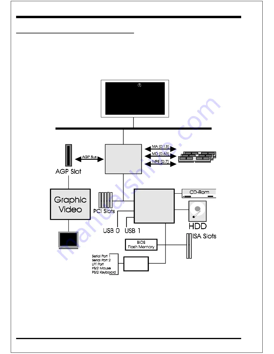
Figure 5: System Block Diagram
System Block Diagram
P e n tiu m II o r
D e s c h u te s
P ro c e s s o r
PC I Bridg e
a nd m e m ory
c ontrolle r
VT8 2 C 6 9 3
VT8 2 C 5 9 6 A
I/O Brid g e
1 0 0 /6 6 M H z
1 0 0 /6 6 M H z
6 6 M H z
Win bo nd
8 3 9 7 7 TF


