maxon motor control
EPOS Positioning Controller
EPOS Application Note: Interpolation Position Mode
18
maxon motor control
Edition December 2008 / Subject to change
3.7
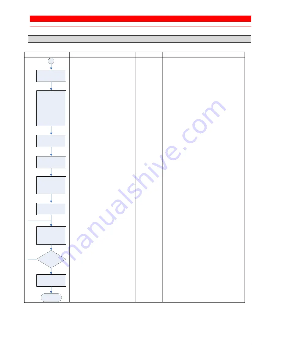
Typical IPM commanding sequence
Diagram
Object name
Object
User value [default value]
Modes of Operation
0x6060-00
0x07 (Interpolated Position Mode)
Max. Following Error
Min. Position Limit
Max. Position Limit
Max. Profile Velocity
Max. Acceleration
Profile Velocity
Profile Acceleration
Quick Stop Deceleration
0x6065-00
0x607D-01
0x607D-02
0x607F-00
0x60C5-00
0x6081-00
0x6083-00
0x6084-00
Application specific [2000 qc]
Application specific [-2147483648 qc]
Application specific [2147483647 qc]
Motor specific [25000 rpm]
Application specific [4294967295 rpm/s]
Application specific [1000 rpm]
Application specific [10000 rpm/s]
Application specific [10000 rpm/s]
Controlword (Shutdown)
Controlword (SwitchOn)
0x6040-00
0x6040-00
0x0006
0x000F
Buffer clear
0x60C4-06
0x01
Interpolation data record
0x20C1-00
Reference points (PVT)
(minimum 2 points!)
Controlword (enable ip mode)
0x6040-00
0x001F
if (Interpolation buffer status)
do
Interpolation data record
until (Interpolation buffer status)
0x20C4-01
0x20C1-00
0x20C4-01
Bit 0 == 1 (Underflow Warning)
Reference point (PVT)
Bit 1 == 1 (Overflow Warning)
Interpolation data record
0x20C1-00
Reference point (PVT) with time = 0
Set Operation
Mode
Set Parameters
Enable Device
Enable Buffer
access
Feed Reference
Points
Activate
Interpolation
Feed Reference
Points
End
More Points?
Feed Profile End
Yes
Table 17:
Typical Commanding sequence
During the interpolation is active the feeding of new reference points is the main task. To minimize the
communication overhead it makes sense to map the “Interpolation data record” in a (asynchronous) receive PDO. If
the “Interpolation buffer status” is mapped to an event trigger transmit PDO (maybe together with the Statusword)
the processing of the reference point feeding could be implemented simpler.


