


Digitax ST User Guide
23
Issue: 5
4.2 Ground connections
The drive must be connected to the system ground of the AC supply. The
ground wiring must conform to local regulations and codes of practice.
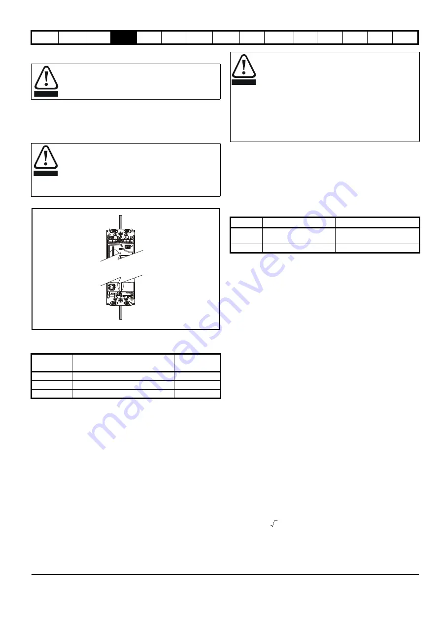
The supply and motor ground connections are made using the M6
threaded hole in the metal back plate of the drive located at the top and
bottom of the drive. See Figure 4-2 for details.
Figure 4-2 Ground connection
4.3 AC supply requirements
Table 4-1 Supply requirements
*Maximum supply in-balance: 2 % negative phase sequence (equivalent
to 3 % voltage in-balance between phases).
For UL compliance only, the maximum supply symmetrical fault current
must be limited to 100 kA.
4.3.1 Supply types
All drives are suitable for use on any supply type i.e TN-S, TN-C-S, TT
and IT.
•
Supplies with voltage up to 600 V may have grounding at any
potential, i.e. neutral, centre or corner (“grounded delta”)
•
Supplies with voltage above 600 V may not have corner grounding
Drives are suitable for use on supplies of installation category III and
lower, according to IEC60664-1. This means they may be connected
permanently to the supply at its origin in a building, but for outdoor
installation additional over-voltage suppression (transient voltage surge
suppression) must be provided to reduce category IV to category III.
A ground fault in the supply has no effect in any case. If the motor must
continue to run with a ground fault in its own circuit then an input
isolating transformer must be provided and if an EMC filter is required it
must be located in the primary circuit.
Unusual hazards can occur on ungrounded supplies with more than one
source, for example on ships. Contact the supplier of the drive for more
information.
Table 4-2 Behavior of the drive in the event of a motor circuit
ground (earth) fault with an IT supply
4.3.2 Line reactors
Input line reactors reduce the risk of damage to the drive resulting from
poor phase balance or severe disturbances on the supply network.
Where line reactors are to be used, reactance values of approximately 2
% are recommended. Higher values may be used if necessary, but may
result in a loss of drive output (reduced torque at high speed) because of
the voltage drop.
For all drive ratings, 2 % line reactors permit drives to be used with a
supply imbalance of up to 3.5 % negative phase sequence (equivalent to
5 % voltage imbalance between phases).
Severe disturbances may be caused by the following factors, for
example:
•
Power factor correction equipment connected close to the drive
•
Large DC drives having no or inadequate line reactors connected to
the supply
•
Direct-on-line started motor(s) connected to the supply such that
when any of these motors are started, the voltage dip exceeds 20 %
Such disturbances may cause excessive peak currents to flow in the
input power circuit of the drive. This may cause nuisance tripping, or in
extreme cases, failure of the drive.
Drives of low power rating may also be susceptible to disturbance when
connected to supplies with a high rated capacity.
When required, each drive must have its own reactor(s). Three individual
reactors or a single three-phase reactor should be used.
Reactor current ratings
Continuous current:
Not less than the continuous input current rating of the drive.
Repetitive peak current:
Not less than three times the continuous input current rating of the drive.
4.3.3 Input inductor calculation
To calculate the inductance required (at
Y
%), use the following equation:
Where:
I
= drive rated input current (A)
L
= inductance (H)
f
= supply frequency (Hz)
V
= voltage between lines
Electrochemical corrosion of grounding terminals
Ensure that grounding terminals are protected against
corrosion i.e. as could be caused by condensation.
The ground loop impedance must conform to the
requirements of local safety regulations.
The drive must be grounded by a connection capable of
carrying the prospective fault current until the protective
device (fuse, etc.) disconnects the AC supply.
The ground connections must be inspected and tested at
appropriate intervals.
Model
Voltage
Frequency
range
DST120X
200 V to 240 V
±
10 % single phase
48 Hz to 65 Hz
DST120X
200 V to 240 V
±
10 % three phase*
48 Hz to 65 Hz
DST140X
380 V to 480 V
±
10 % three phase*
48 Hz to 65 Hz
WARNING
WARNING
Supply
ground
Motor
ground
Operation with IT (ungrounded) supplies:
Special attention is required when using internal or external
EMC filters with ungrounded supplies, because in the event
of a ground (earth) fault in the motor circuit the drive may not
trip and the filter could be over-stressed. In this case, either
the filter must not be used (removed) or additional
independent motor ground fault protection must be provided.
Refer to Table 4-2.
For instructions on removal, refer to Figure 4-4 Removing
the internal EMC filter and line to ground varistors
For details of ground fault protection contact the
supplier of the drive.
Drive size
Internal filter only
External filter (with internal)
0 (200 V)
May not trip – precautions
required
Drive trips on fault
0 (400 V)
Drive trips on fault
Drive trips on fault
WARNING
L
Y
100
----------
V
3
-------
×
1
2
π
f
I
------------
×
=


